Dell Dimension 4700C Owner'S Manual Download Page 17

Setting Up and Using Your Computer

17

Network Setup Wizard

The Microsoft

®

 Windows

®

 XP operating system provides a Network Setup Wizard to guide you 

through the process of sharing files, printers, or an Internet connection between computers in a 
home or small office.

1

Click the 

Start

 button, point to 

All Programs

 Accessories

 Communications

, and then 

click 

Network Setup Wizard

.

2

On the welcome screen, click 

Next

.

3

Click 

Checklist for creating a network

.


NOTE: 

Selecting the connection method 

This computer connects directly to the Internet

 enables the 

integrated firewall provided with Windows XP Service Pack 1 (SP1) or later operating systems.

4

Complete the checklist and required preparations.

5

Return to the Network Setup Wizard and follow the instructions on the screen.

Connecting to the Internet


NOTE: 

ISPs and ISP offerings vary by country.

To connect to the Internet, you need a modem or network connection and an Internet service 
provider (ISP), such as AOL or MSN. Your ISP will offer one or more of the following Internet 
connection options:

Dial-up connections that provide Internet access through a telephone line. Dial-up 
connections are considerably slower than DSL and cable modem connections.
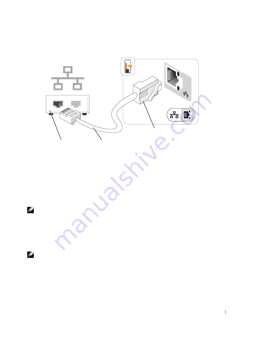
network device

network adapter connector on computer

network cable

network adapter 
connector

Summary of Contents for Dimension 4700C

Page 1: ... card slots 4 optional video card see the setup diagram modem connector USB 2 0 connectors 5 center LFE connector voltage selection switch diagnostic lights 4 integrated video connector power connector microphone connector line in connector SPDIF out connector serial connector network adapter connector line out connector surround connector IEEE 1394 connector Not present on all computers PCI Expre...

Page 2: ...4 Dell Inc All rights reserved Reproduction in any manner whatsoever without the written permission of Dell Inc is strictly forbidden Trademarks used in this text Dell the DELL logo Inspiron DellPrecision Dimension OptiPlex Latitude PowerEdge PowerVault PowerApp DellNet and PowerConnect are trademarks of Dell Inc Intel Pentium and Celeron are registered trademarks of Intel Corporation Microsoft Wi...

Page 3: ...Settings 16 Setting Up a Home and Office Network 16 Connecting to a Network Adapter 16 Network Setup Wizard 17 Connecting to the Internet 17 Setting Up Your Internet Connection 18 Playing a CD or DVD 19 Adjusting the Volume 21 Adjusting the Picture 21 Copying CDs and DVDs 21 How to Copy a CD or DVD 21 Using Blank CD Rs CD RWs DVD R and DVD RW 22 Helpful Tips 22 Power Management 23 Standby Mode 23 ...

Page 4: ...es not start up 32 The computer stops responding 33 A program stops responding 33 A program crashes repeatedly 33 A program is designed for an earlier Windows operating system 33 A solid blue screen appears 33 Other software problems 34 Memory Problems 34 Mouse Problems 35 Network Problems 36 Power Problems 36 Printer Problems 37 Scanner Problems 38 Sound and Speaker Problems 39 No sound from spea...

Page 5: ... Microsoft Windows XP System Restore 50 4 Removing and Installing Parts Before You Begin 53 Recommended Tools 53 Turning Off Your Computer 53 Before Working Inside Your Computer 53 Front and Back View of the Computer 54 Front View 54 Back View 56 Reattaching the Front Door 58 Opening the Computer Cover 59 Inside View Of Your Computer 60 System Board Components 62 Memory 63 DDR2 Memory Overview 63 ...

Page 6: ... Computer Cover 80 5 Appendix Specifications 81 System Setup 85 Overview 85 Entering System Setup 86 System Setup Options 87 Boot Sequence 90 Clearing Forgotten Passwords 91 Clearing CMOS Settings 92 Cleaning Your Computer 93 Computer Keyboard and Monitor 93 Mouse 93 CDs and DVDs 93 Dell Technical Support Policy U S Only 94 Definition of Dell Installed Software and Peripherals 94 Definition of Thi...

Page 7: ...Contents 7 FCC Notices U S Only 95 Class A 95 Class B 95 FCC Identification Information 96 Contacting Dell 96 Index 113 ...

Page 8: ...8 Contents ...

Page 9: ...s and Conditions Dell Product Information Guide How to set up my computer Setup Diagram Express Service Code and Service Tag Microsoft Windows License Label Express Service Code and Product Key Label These labels are located on your computer Use the Service Tag to identify your computer when you use support dell com or contact technical support Enter the Express Service Code to direct your call wh...

Page 10: ...es Community Forum Online discussion with other Dell customers Upgrades Upgrade information for components such as memory the hard drive and the operating system Customer Care Contact information order status warranty and repair information Downloads Drivers patches and software updates Reference Computer documentation product specifications and white papers How to use Windows XP Documentation for...

Page 11: ...ion follow the safety instructions in the Product Information Guide NOTE Place your computer on a soft surface to prevent scratching the top cover To attach the stand 1 Rotate the computer to an upside down position 2 Insert the screw into the bottom of the stand 3 Align the two tabs and the screw on the stand with the tab holes and screw hole in the bottom of the computer ...

Page 12: ...12 Setting Up and Using Your Computer w w w d e l l c o m s u p p o r t d e l l c o m tabs 2 tab holes 2 screw screw hole ...

Page 13: ...omputer in a horizontal position until you reattach the stand Setting Up a Printer NOTICE Complete the operating system setup before you connect a printer to the computer See the documentation that came with the printer for setup information including how to Obtain and install updated drivers Connect the printer to the computer Load paper and install the toner or ink cartridge Contact the printer ...

Page 14: ... You can connect USB devices while the computer is turned on 1 Complete the operating system setup if you have not already done so 2 Install the printer driver if necessary See the documentation that came with your printer 3 Attach the USB printer cable to the USB connectors on the computer and the printer The USB connectors fit only one way Using a Media Card Reader Use the Media Card Reader to t...

Page 15: ...nnector If you encounter resistance do not force the media or card Check the card orientation and try again Connecting a TV NOTE To connect a TV to your computer you must purchase an S video cable which is available at most consumer electronics stores An S video cable is not included with your computer 1 Follow the procedures in Before You Begin on page 53 2 Connect one end of the S video cable to...

Page 16: ... on changing the display settings for your graphics card see the user s guide in the Help and Support Center click the Start button click Help and Support click User and system guides click Device guides and then click the guide for your graphics card Setting Up a Home and Office Network Connecting to a Network Adapter NOTE Plug the network cable into the network adapter connector on the computer ...

Page 17: ...the integrated firewall provided with Windows XP Service Pack 1 SP1 or later operating systems 4 Complete the checklist and required preparations 5 Return to the Network Setup Wizard and follow the instructions on the screen Connecting to the Internet NOTE ISPs and ISP offerings vary by country To connect to the Internet you need a modem or network connection and an Internet service provider ISP s...

Page 18: ...n the screen to complete the setup If you do not have an MSN Explorer or AOL icon on your desktop or if you want to set up an Internet connection with a different ISP 1 Save and close any open files and exit any open programs 2 Click the Start button and click Internet Explorer The New Connection Wizard appears 3 Click Connect to the Internet 4 In the next window click the appropriate option If yo...

Page 19: ...e service status or try connecting again later Playing a CD or DVD NOTICE Do not press down on the CD or DVD tray when you open or close it Keep the tray closed when you are not using the drive NOTICE Do not move the computer when you are playing CDs or DVDs 1 Press the eject button on the front of the drive 2 Place the disc label side up in the center of the tray 3 Press the disc into the center ...

Page 20: ... create CDs A CD player includes the following basic buttons A DVD player includes the following basic buttons For more information on playing CDs or DVDs click Help on the CD or DVD player if available Play Move backward within the current track Pause Move forward within the current track Stop Go to the previous track Eject Go to the next track Stop Play Fast forward Pause Fast reverse Go to the ...

Page 21: ...ow click and drag the bar in Screen resolution to change the setting to 800 by 600 pixels 5 Click the drop down menu under Color quality and then click Medium 16 bit 6 Click OK Copying CDs and DVDs NOTE Ensure that you follow all copyright laws when you create CDs or DVDs This section applies only to computers that have a CD R DVD RW DVD R or DVD CD RW combo drive NOTE The types of CD or DVD drive...

Page 22: ...l drives select the drive into which you have inserted your source CD or DVD disc and click Copy The computer copies the data on the CD or DVD to the blank CD or DVD After you finish copying the source CD or DVD the CD or DVD that you created automatically ejects Using Blank CD Rs CD RWs DVD R and DVD RW Use blank CD Rs to record music or permanently store data files After creating a CD R disc you...

Page 23: ...ernate mode to reduce power to the entire computer When the computer exits from a power conservation mode the Windows desktop is restored to the state it was in before it entered the mode NOTE Windows XP Professional includes security and networking features not available in Windows XP Home Edition When a Windows XP Professional computer is connected to a network different options related to secur...

Page 24: ...ile before shipping the computer to you If the computer s hard drive becomes corrupted Windows XP recreates the hibernate file automatically Power Options Properties Define your standby mode settings hibernate mode settings and other power settings in the Power Options Properties window To access the Power Options Properties window 1 Click the Start button and click Control Panel 2 Under Pick a ca...

Page 25: ...ve Advanced Tab The Advanced tab allows you to Place the power options icon in the Windows taskbar for quick access Set the computer to prompt you for your Windows password before the computer exits from standby mode or hibernate mode Program the power button to activate standby mode activate hibernate mode or turn off the computer To program these functions click an option from the corresponding ...

Page 26: ...nufacturer Contact the software manufacturer for updates and information about using Hyper Threading with your software To determine if your computer is using Hyper Threading technology 1 Click the Start button right click My Computer and then click Properties 2 Click Hardware and click Device Manager 3 In the Device Manager window click the plus sign next to Processors If Hyper Threading is enabl...

Page 27: ...ded by the manufacturer Discard used batteries according to the manufacturer s instructions CAUTION Before you begin any of the procedures in this section follow the safety instructions located in the Product Information Guide Drive Problems CAUTION Before you begin any of the procedures in this section follow the safety instructions located in the Product Information Guide REPLACE THE BATTERY If ...

Page 28: ... OR DISK See page 93 CHECK THE CABLE CONNECTIONS RUN THE HARDWARE TROUBLESHOOTER See page 50 RUN THE DELL DIAGNOSTICS See page 46 ADJUST THE WINDOWS VOLUME CONTROL Click the speaker icon in the lower right corner of your screen Ensure that the volume is turned up by clicking the slidebar and dragging it up Ensure that the sound is not muted by clicking any boxes that are checked CHECK THE SPEAKERS...

Page 29: ...k CHECK THE TELEPHONE LINE CONNECTION CHECK THE TELEPHONE JACK CONNECT THE MODEM DIRECTLY TO THE TELEPHONE WALL JACK USE A DIFFERENT TELEPHONE LINE Verify that the telephone line is connected to the jack on the modem The jack has either a green label or a connector shaped icon next to it Ensure that you hear a click when you insert the telephone line connector into the modem Disconnect the telepho...

Page 30: ...NECTED TO THE INTERNET Ensure that you have subscribed to an Internet provider With the Outlook Express e mail program open click File If Work Offline has a checkmark next to it click the checkmark to remove it and connect to the Internet For help contact your Internet service provider A FILENAME CANNOT CONTAIN ANY OF THE FOLLOWING CHARACTERS Do not use these characters in filenames A REQUIRED DLL...

Page 31: ...eader the device is automatically assigned a drive letter as the next logical drive after all other physical drives in the system If the next logical drive after the physical drives is mapped to a network drive Windows XP does not automatically assign a drive letter to the Media Card Reader To manually assign a drive for the Media Card Reader 1 Right click My Computer and select Manage 2 Select th...

Page 32: ...ted Windows recognizes the device IF YOU HAVE PROBLEMS WITH A DELL IEEE 1394 DEVICE Contact Dell see page 96 IF YOU HAVE PROBLEMS WITH A NON DELL IEEE 1394 DEVICE Contact the manufacturer of the IEEE 1394 device CHECK THE KEYBOARD CABLE Ensure that the keyboard cable is firmly connected to the computer Reconnect the keyboard cable as shown on the setup diagram for your computer Check the cable con...

Page 33: ...er END THE PROGRAM 1 Press Ctrl Shift Esc simultaneously 2 Click Applications 3 Click the program that is no longer responding 4 Click End Task CHECK THE SOFTWARE DOCUMENTATION If necessary uninstall and then reinstall the program RUN THE PROGRAM COMPATIBILITY WIZARD The Program Compatibility Wizard configures a program so it runs in an environment similar to non Windows XP operating system enviro...

Page 34: ...at the program is installed and configured properly Verify that the device drivers do not conflict with the program If necessary uninstall and then reinstall the program BACK UP YOUR FILES IMMEDIATELY USE A VIRUS SCANNING PROGRAM TO CHECK THE HARD DRIVE FLOPPY DISKS OR CDS SAVE AND CLOSE ANY OPEN FILES OR PROGRAMS AND SHUT DOWN YOUR COMPUTER THROUGH THE START MENU IF YOU RECEIVE AN INSUFFICIENT ME...

Page 35: ...ble connector for damaged or frayed cables 2 Remove mouse extension cables if used and connect the mouse directly to the computer 3 Reconnect the mouse cable as shown on the setup diagram for your computer RESTART THE COMPUTER 1 Simultaneously press Ctrl Esc to display the Start menu 2 Type u press the keyboard arrow keys to highlight Shut down or Turn Off and then press Enter 3 After the computer...

Page 36: ...GHTS ON THE BACK OF THE COMPUTER If the link integrity light is off that indicates no network communication exists Replace the network cable For a description of network lights see Controls and Lights on page 84 RESTART THE COMPUTER AND LOG ON TO THE NETWORK AGAIN CHECK YOUR NETWORK SETTINGS Contact your network administrator or the person who set up your network to verify that your network settin...

Page 37: ... that the main power cable and front panel cable are securely connected to the system board see page 62 IF THE POWER LIGHT IS STEADY AMBER A device might be malfunctioning or incorrectly installed Remove and then reinstall the memory modules see page 63 Remove and then reinstall any cards see page 66 Remove and then reinstall the graphics card if applicable see page 66 IF THE POWER LIGHT IS BLINKI...

Page 38: ...THE PRINTER IS RECOGNIZED BY WINDOWS 1 Click the Start button click Control Panel and then click Printers and Other Hardware 2 Click View installed printers or fax printers If the printer is listed right click the printer icon 3 Click Properties and click the Ports tab For a USB printer ensure that the Print to the following port s setting is USB REINSTALL THE PRINTER DRIVER See the printer docume...

Page 39: ...rs are connected as shown on the setup diagram supplied with the speakers If you purchased a sound card ensure that the speakers are connected to the card ENSURE THAT THE SUBWOOFER AND THE SPEAKERS ARE TURNED ON See the setup diagram supplied with the speakers If your speakers have volume controls adjust the volume bass or treble to eliminate distortion ADJUST THE WINDOWS VOLUME CONTROL Click or d...

Page 40: ...S VOLUME CONTROL Click or double click the speaker icon in the lower right corner of your screen Ensure that the volume is turned up and that the sound is not muted CHECK THE MONITOR CABLE CONNECTION Ensure that the graphics cable is connected as shown on the setup diagram for your computer If you are using a graphics extension cable and removing the cable solves the problem the cable is defective...

Page 41: ...HE MONITOR If your speaker system includes a subwoofer ensure that the subwoofer is at least 60 cm 2 ft away from the monitor MOVE THE MONITOR AWAY FROM EXTERNAL POWER SOURCES Fans fluorescent lights halogen lamps and other electrical devices can cause the screen image to appear shaky Turn off nearby devices to check for interference ROTATE THE MONITOR TO ELIMINATE SUNLIGHT GLARE AND POSSIBLE INTE...

Page 42: ...42 Solving Problems w w w d e l l c o m s u p p o r t d e l l c o m ...

Page 43: ...yellow or green When the computer starts normally the lights flash After the computer starts all four lights display solid green If the computer malfunctions the color and sequence of the lights identify the problem Light Pattern Problem Description Suggested Resolution The computer is in a normal off condition or a possible pre BIOS failure has occurred Plug the computer into a working electrical...

Page 44: ...f the problem persists contact Dell see page 96 A possible graphics card failure has occurred If the computer has a graphics card remove the card reinstall it see page 66 and then restart the computer If the problem still exists install a graphics card that you know works and restart the computer If the problem persists or the computer has integrated graphics contact Dell see page 96 A possible fl...

Page 45: ...ory module memory connector placement requirements exist see page 63 Verify that the memory modules that you are installing are compatible with your computer see page 63 If the problem persists contact Dell see page 96 A possible expansion card failure has occurred 1 Determine if a conflict exists by removing a card not a graphics card see page 66 and restarting the computer 2 If the problem persi...

Page 46: ...desktop Then shut down your computer see page 53 and try again 3 When the boot device list appears highlight Boot to Utility Partition and press Enter Another failure has occurred Ensure that the cables are properly connected to the system board from the hard drive CD drive and DVD drive see page 62 If there is an error message on your screen identifying a problem with a device such as the floppy ...

Page 47: ...ee option click the applicable tab described in the following table for more information Option Function Express Test Performs a quick test of devices This test typically takes 10 to 20 minutes and requires no interaction on your part Run Express Test first to increase the possibility of tracing the problem quickly Extended Test Performs a thorough check of devices This test typically takes an hou...

Page 48: ... install drivers if you Upgrade your operating system Reinstall your operating system Connect or install a new device Identifying Drivers If you experience a problem with any device identify whether the driver is the source of your problem and if necessary update the driver Windows XP 1 Click the Start button and click Control Panel 2 Under Pick a Category click Performance and Maintenance 3 Click...

Page 49: ...Properties window click the Hardware tab 5 Click Device Manager 6 Right click the device for which the new driver was installed and click Properties 7 Click the Drivers tab 8 Click Roll Back Driver If Device Driver Rollback does not resolve the problem then use System Restore to return your computer to the operating state that existed before you installed the new driver Manually Reinstalling Drive...

Page 50: ...he computer Dell PC Restore permanently deletes all data on the hard drive and removes any applications installed after you received the computer Using Microsoft Windows XP System Restore The Microsoft Windows XP operating system provides System Restore to allow you to return your computer to an earlier operating state without affecting data files if changes to the hardware software or other syste...

Page 51: ...tore point that you prefer 5 Click Next The Restoration Complete screen appears after System Restore finishes collecting data and then the computer restarts 6 After the computer restarts click OK To change the restore point you can either repeat the steps using a different restore point or you can undo the restoration Undoing the Last System Restore NOTICE Before you undo the last system restore s...

Page 52: ...store To use PC Restore 1 Turn on the computer During the boot process a blue bar with www dell com appears at the top of the screen 2 Immediately upon seeing the blue bar press Ctrl F11 If you do not press Ctrl F11 in time let the computer finish restarting and then restart the computer again NOTICE If you do not want to proceed with PC Restore click Reboot in the following step 3 On the next scr...

Page 53: ...mall flat blade screwdriver Phillips screwdriver Turning Off Your Computer NOTICE To avoid losing data save and close any open files and exit any open programs before you turn off your computer 1 Shut down the operating system a Save and close any open files exit any open programs click the Start button and then click Turn Off Computer b In the Turn off computer window click Turn off The computer ...

Page 54: ...avoid damaging the computer perform the following steps before you begin working inside the computer 1 Turn off your computer see page 53 NOTICE To disconnect a network cable first unplug the cable from your computer and then unplug it from the network wall jack 2 Disconnect any telephone or network cables from the computer 3 Disconnect your computer and all attached devices from their electrical ...

Page 55: ...ilable on computers with an optional Media Card Reader 5 USB 2 0 connectors 2 Use the front USB connectors for devices that you connect occasionally such as joysticks or cameras It is recommended that you use the back USB connectors for devices that typically remain connected such as printers and keyboards NOTICE This computer supports the use of a USB hub However do not connect two or more USB hu...

Page 56: ... operating 8 power button Press to turn on the computer NOTICE To avoid losing data do not use the power button to turn off the computer Instead perform an operating system shutdown 9 front panel door Open the door to use the front panel connectors NOTE The front door is removable if you remove it or accidentally knock it off its hinges it snaps back in place For instructions on how to reattach th...

Page 57: ...r Plug the cable from your monitor into the video card connector This feature is only available on computers with an optional video card 10 center LFE connector Use the yellow center LFE connector to attach your subwoofer and center channel 11 SPDIF out connector Use this connector to provide a digital audio signal to amplifiers a mini disc and other SPDIF in compatible equipment 12 microphone con...

Page 58: ...CE To disconnect a network cable first unplug the cable from your computer and then unplug it from the network wall jack 3 Disconnect any telephone or telecommunication lines from the computer 4 Disconnect your computer and all attached devices from their electrical outlets and then press the power button to ground the system board NOTE The top hinge arm clicks when it is moved to the closed posit...

Page 59: ...ter and all attached devices from their electrical outlets and then press the power button to ground the system board 5 Remove the computer stand if it is attached see page 11 CAUTION To guard against electrical shock always unplug your computer from the electrical outlet before opening the cover NOTICE Ensure that there is sufficient space to support the open cover at least 30 cm 1 ft of desk top...

Page 60: ...w the safety instructions in the Product Information Guide CAUTION To guard against electrical shock always unplug your computer from the electrical outlet before opening the cover NOTICE Be careful when opening the computer cover to ensure that you do not inadvertently disconnect cables from the system board release buttons one on each side back of computer cable security tab ...

Page 61: ...Removing and Installing Parts 61 hard drive card slots power supply heat sink and blower assembly system board CD or DVD drive back of computer ...

Page 62: ...front panel connector FRONT PANEL front panel 1394 connector for Media Card Reader FP1394 PCI Express x1 card connector PCI_E1 processor power connector 12V POWER processor and heat sink connector memory module connectors DIMM_1 and DIMM_2 password jumper PSWD modem MDC1 processor fan connector FAN front panel audio connector FRONTAUDIO Standby Voltage Indicator AUX_PWR main power connector POWER ...

Page 63: ...tched pair the computer will continue to operate but with a slight reduction in performance If you install a mixed pair of DDR2 400 MHz PC2 3200 and DDR2 533 MHz PC2 4300 memory the modules function at the slowest speed installed See the label on the module to determine the module s capacity NOTE Always install DDR2 memory modules in the order indicated on the system board NOTICE Do not install EC...

Page 64: ... of memory available to the operating system is slightly less than 4 GB Certain components within the computer require address space in the 4 GB range Any address space reserved for these components cannot be used by computer memory Installing Memory CAUTION Before you begin any of the procedures in this section follow the safety instructions located in the Product Information Guide NOTICE To prev...

Page 65: ...sition If you insert the module correctly the securing clips snap into the cutouts at each end of the module 6 Close the computer cover NOTICE To connect a network cable first plug the cable into the network device and then plug it into the computer 7 Connect your computer and devices to electrical outlets and turn them on 8 Right click the My Computer icon and click Properties 9 Click the General...

Page 66: ...o remove gently ease the module back and forth to remove it from the connector Cards CAUTION Before you begin any of the procedures in this section follow the safety instructions located in the Product Information Guide NOTICE To prevent static damage to components inside your computer discharge static electricity from your body before you touch any of your computer s electronic components You can...

Page 67: ... on page 70 If you are replacing a card remove the current driver for the card from the operating system Installing a PCI Express Card 1 Follow the procedures in Before You Begin on page 53 2 Press the lever on the card retention arm and raise the retention arm 3 If you are installing a new card remove the filler bracket to create a card slot opening Then continue with step 6 retention arm filler ...

Page 68: ...nstalled in the computer remove the card If necessary disconnect any cables connected to the card Gently pull the securing tab grasp the card by its top corners and then ease it out of its connector edge connector card connector securing tab securing slot edge connector card connector x16 card x1 card retention arm retention arm ...

Page 69: ...uter from its electrical outlet before installing any cards 6 If you are installing the card into the x16 card connector position the card so the securing slot is aligned with the securing tab and gently pull the securing tab 7 Place the card in the connector and press down firmly Ensure that the card is fully seated in the slot 8 Ensure that The tops of all cards and filler brackets are flush wit...

Page 70: ...computer cover reconnect the computer and devices to electrical outlets and then turn them on 12 Install any drivers required for the card as described in the card documentation Removing a PCI Express Card 1 Follow the procedures in Before You Begin on page 53 2 If necessary disconnect any cables connected to the card 3 Gently pull back the securing tab grasp the card by its top corners and then e...

Page 71: ... Removing a Media Card Reader CAUTION Before you begin any of the procedures in this section follow the safety instructions located in the Product Information Guide NOTICE To prevent static damage to components inside your computer discharge static electricity from your body before you touch any of your computer s electronic components You can do so by touching an unpainted metal surface on the co...

Page 72: ...he computer cover see page 80 Installing a Media Card Reader CAUTION Before you begin any of the procedures in this section follow the safety instructions located in the Product Information Guide NOTICE To prevent static damage to components inside your computer discharge static electricity from your body before you touch any of your computer s electronic components You can do so by touching an un...

Page 73: ...g 6 Make sure the USB cable and IEEE 1394 cable are connected to the back of the Media Card Reader 7 Connect the USB cable on the back of the Media Card Reader to the front panel USB connector on the system board see page 62 8 Connect the IEEE 1394 cable on the back of the Media Card Reader to the front panel IEEE 1394 connector on the system board see page 62 CD drive cable CD drive ...

Page 74: ...llow the safety instructions in the Product Information Guide NOTICE Before you remove or install the modem make sure to disconnect all telephone and network cables from your computer NOTICE To prevent static damage to components inside your computer discharge static electricity from your body before you touch any of your computer s electronic components You can do so by touching an unpainted meta...

Page 75: ...you feel resistance check the connectors and realign the card 4 Install the new modem a Align the modem with the screw holes and press the modem into the connector on the system board b Replace the ground wire c Use a size 1 screwdriver to install the screws that secure the modem and ground wire to the system board d Connect the modem cable to the modem 5 Close the computer cover see page 80 Repla...

Page 76: ...mputer chassis 1 Follow the procedures in Before You Begin on page 53 2 Open the computer cover see page 59 3 Remove the modem cable and ground wire from the modem a Disconnect the modem cable from the modem b Remove the screw that secures the ground wire to the modem and system board and set the screw aside c Remove the cable and ground wire from the securing clip that is located next to the mode...

Page 77: ...external clip completely engages and fits tightly against the back of the computer d Place the modem cable and ground wire in the cable clip and secure the clip to the computer chassis with the screw e Carefully route the cable and ground wire around the processor making sure that you keep the wires away from any internal parts 6 Attach the modem cable and ground wire to the modem a Connect the mo...

Page 78: ... the manufacturer Discard used batteries according to the manufacturer s instructions To replace the coin cell battery NOTE For information regarding the type of coin cell battery see Power on page 84 1 Record all the screens in system setup see page 85 so that you can restore the correct settings in step 8 2 Follow the procedures in Before You Begin on page 53 3 Locate the battery socket see page...

Page 79: ...ry a Support the battery connector by pressing down firmly on the positive side of the connector b Hold the battery with the facing up and slide it under the securing tabs at the positive side of the connector c Press the battery straight down into the connector until it snaps into place 6 Close the computer cover see page 80 battery positive side negative side of battery battery socket ...

Page 80: ...s section follow the safety instructions located in the Product Information Guide 1 Ensure that all cables are connected and fold cables out of the way Gently pull the power cables toward you so that they do not get caught underneath the drives 2 Ensure that no tools or extra parts are left inside the computer 3 Close the cover a Pivot the cover down b Press down on the right side of the cover unt...

Page 81: ...B for Pentium 4 processors 256 KB for Celeron processors depending on your computer configuration pipelined burst eight way set associative write back SRAM Memory Type 400 MHz and 533 MHz DDR2 unbuffered SDRAM Memory connectors two Memory capacities 256 MB 512 MB 1 GB or 2 GB non ECC Minimum memory 256 MB Maximum memory 4 GB NOTE See Addressing Memory With 4 GB Configurations in your Owner s Manua...

Page 82: ...directional speed 500 MB s x16 slot bidirectional speed 8 GB sec PCI Express connector one x1 connector size 36 pins connector data width maximum one PCI Express lane PCI Express connector one x16 connector size 164 pins connector data width maximum 16 PCI Express lanes Drives Externally accessible one slimline 3 5 inch media bay one slimline 5 25 inch drive bay Available devices Serial ATA drive ...

Page 83: ...d center Low Frequency Effects LFE channel S PDIF back panel connector S PDIF connector not present on all computers Network adapter RJ45 connector Modem RJ11 MDC 1 5 connector System board connectors IDE drive one 40 pin connector Serial ATA one 7 pin connectors Fan one 5 pin connectors PCI Express x1 36 pin connector PCI Express x16 164 pin connector USB 8 pin header for optional Media Card Read...

Page 84: ... and the computer off no light The computer is not detecting a physical connection to the network Activity light on integrated network adapter yellow blinking light Diagnostic lights four lights on the back panel See Diagnostic Lights in your Dell Dimension Owner s Manual Standby power light AUX_PWR on the system board Activity light optional Media Card Reader green blinking light Power DC power s...

Page 85: ...ight 7 4 kg 16 4 lb Environmental Temperature Operating 10 to 35 C 50 to 95 F NOTE At 35 C 95 F the maximum operating altitude is 914 m 3000 ft Storage 40 to 65 C 40 to 149 F Relative humidity 20 to 80 noncondensing Maximum vibration Operating 0 25 G at 3 to 200 Hz at 0 5 octave min Storage 0 5 G at 3 to 200 Hz at 1 octave min Maximum shock Operating bottom half sine pulse with a change in velocit...

Page 86: ... is divided into three areas the options list active options field and key functions Options List This field appears on the left side of the system setup window The field is a scrollable list containing features that define the configuration of your computer including installed hardware power conservation and security features Scroll up and down the list with the up and down arrow keys As an optio...

Page 87: ...first device in the list Drives Diskette Drive Identifies and defines the floppy drive attached to the FLOPPY connector on the system board as Off USB Internal or Read Only Drives 0 through 1 Identifies the drives attached to the SATA or PRI IDE connectors on the system board and lists the capacity for hard drives SATA Operation Identifies and defines the SATA modes You can set the SATA controller...

Page 88: ...perates at the level suggested by the drive manufacturer Performance The hard drive operates at its maximum speed NOTE Switching to performance mode may cause the drive to be noisier but its performance is not affected NOTE Changing the acoustics setting does not alter your hard drive image Security This section displays available system security options DEP Execute Disable Opt In default DEP is e...

Page 89: ... Sets time to automatically turn on the computer Time is kept in a 24 hour format hours minutes Change the start up time by pressing the right or left arrow key to increase or decrease the numbers or type numbers in both the date and time fields This feature does not work if you turn off your computer using a power strip or surge protector Low Power Mode Use this mode to conserve power Suspend Mod...

Page 90: ... F12 The BIOS detects the device and adds the USB flash option to the boot menu NOTE To boot to a USB device the device must be bootable To make sure that your device is bootable check the device documentation Changing Boot Sequence for the Current Boot You can use this feature for example to restart your computer to a USB device such as a floppy drive or memory key 1 If you are booting to a USB d...

Page 91: ... up and down arrow keys to move through the list of devices 4 Press the spacebar to enable or disable a device enabled devices have a checkmark 5 Press the U key or the D key to move a selected device up or down the list Clearing Forgotten Passwords CAUTION Before you begin any of the procedures in this section follow the safety instructions located in the Product Information Guide 1 Follow the pr...

Page 92: ...k cable first plug the cable into the network device and then plug it into the computer 11 Connect your computer and devices to electrical outlets and turn them on Clearing CMOS Settings CAUTION Before you begin any of the procedures in this section follow the safety instructions located in the Product Information Guide 1 Follow the procedures in Before You Begin on page 53 2 Reset the current CMO...

Page 93: ...ipe the keyboard computer and plastic part of the monitor with a soft cleaning cloth moistened with a solution of three parts water and one part dishwashing detergent Do not soak the cloth or let water drip inside your computer or keyboard Mouse If your screen cursor skips or moves abnormally clean the mouse To clean a non optical mouse 1 Turn the retainer ring on the underside of your mouse count...

Page 94: ... at support dell com Additional technical support options may be available for purchase Dell provides limited technical support for the computer and any Dell installed software and peripherals1 Support for third party software and peripherals is provided by the original manufacturer including those purchased and or installed through Dell Software and Peripherals Readyware and Custom Factory Integr...

Page 95: ...ion is subject to the following two conditions This device may not cause harmful interference This device must accept any interference received including interference that may cause undesired operation Class A This equipment has been tested and found to comply with the limits for a Class A digital device pursuant to Part 15 of the FCC Rules These limits are designed to provide reasonable protectio...

Page 96: ... covered in this document in compliance with FCC regulations Model number DHP Company name Dell Inc One Dell Way Round Rock Texas 78682 USA 512 338 4400 Contacting Dell To contact Dell electronically you can access the following websites www dell com support dell com technical support premiersupport dell com technical support for educational government healthcare and medium large business customer...

Page 97: ...mer Care toll free 0 800 444 0730 Tech Support toll free 0 800 444 0733 Tech Support Services toll free 0 800 444 0724 Sales 0 810 444 3355 Aruba General Support toll free 800 1578 Australia Sydney International Access Code 0011 Country Code 61 City Code 2 E mail Australia au_tech_support dell com E mail New Zealand nz_tech_support dell com Home and Small Business 1 300 65 55 33 Government and Bus...

Page 98: ...or French Speaking Customers support euro dell com be fr emaildell Technical Support 02 481 92 88 Technical Support Fax 02 481 92 95 Customer Care 02 713 15 65 Corporate Sales 02 481 91 00 Fax 02 481 92 99 Switchboard 02 481 91 00 Bermuda General Support 1 800 342 0671 Bolivia General Support toll free 800 10 0238 Brazil International Access Code 00 Country Code 55 City Code 51 Website www dell co...

Page 99: ... 4096 Technical Support med large bus government toll free 1 800 387 5757 Sales Home Sales Small Business toll free 1 800 387 5752 Sales med large bus government toll free 1 800 387 5755 Spare Parts Sales Extended Service Sales 1 866 440 3355 Cayman Islands General Support 1 800 805 7541 Chile Santiago Country Code 56 City Code 2 Sales Customer Support and Technical Support toll free 1230 020 4823...

Page 100: ... toll free 800 858 2557 Large Corporate Accounts GCP toll free 800 858 2055 Large Corporate Accounts Key Accounts toll free 800 858 2628 Large Corporate Accounts North toll free 800 858 2999 Large Corporate Accounts North Government and Education toll free 800 858 2955 Large Corporate Accounts East toll free 800 858 2020 Large Corporate Accounts East Government and Education toll free 800 858 2669...

Page 101: ...en_support dell com E mail Support servers Nordic_server_support dell com Technical Support 7023 0182 Customer Care Relational 7023 0184 Home Small Business Customer Care 3287 5505 Switchboard Relational 3287 1200 Switchboard Fax Relational 3287 1201 Switchboard Home Small Business 3287 5000 Switchboard Fax Home Small Business 3287 5001 Dominica General Support toll free 1 866 278 6821 Dominican R...

Page 102: ...ional Access Code 00 Country Code 33 City Codes 1 4 Website support euro dell com E mail support euro dell com fr fr emaildell Home and Small Business Technical Support 0825 387 270 Customer Care 0825 823 833 Switchboard 0825 004 700 Switchboard calls from outside of France 04 99 75 40 00 Sales 0825 004 700 Fax 0825 004 701 Fax calls from outside of France 04 99 75 40 01 Corporate Technical Suppor...

Page 103: ...Switchboard 2108129810 Gold Service Switchboard 2108129811 Sales 2108129800 Fax 2108129812 Grenada General Support toll free 1 866 540 3355 Guatemala General Support 1 800 999 0136 Guyana General Support toll free 1 877 270 4609 Hong Kong International Access Code 001 Country Code 852 Website support ap dell com E mail apsupport dell com Technical Support Dimension and Inspiron 2969 3188 Technical...

Page 104: ...are dial within U K only 0870 907 4499 Ireland Sales 01 204 4444 U K Sales dial within U K only 0870 907 4000 Fax Sales Fax 01 204 0103 Switchboard 01 204 4444 Italy Milan International Access Code 00 Country Code 39 City Code 02 Website support euro dell com E mail support euro dell com it it emaildell Home and Small Business Technical Support 02 577 826 90 Customer Care 02 696 821 14 Fax 02 696 ...

Page 105: ...044 556 3490 24 Hour Automated Order Service 044 556 3801 Customer Care 044 556 4240 Business Sales Division up to 400 employees 044 556 1465 Preferred Accounts Division Sales over 400 employees 044 556 3433 Large Corporate Accounts Sales over 3500 employees 044 556 3430 Public Sales government agencies educational institutions and medical institutions 044 556 1469 Global Segment Japan 044 556 346...

Page 106: ...stomer Care Brussels Belgium 02 481 91 19 Fax Brussels Belgium 02 481 92 99 Switchboard Brussels Belgium 02 481 91 00 Macao Country Code 853 Technical Support toll free 0800 582 Customer Service Penang Malaysia 604 633 4949 Transaction Sales toll free 0800 581 Malaysia Penang International Access Code 00 Country Code 60 City Code 4 Technical Support Dell Precision OptiPlex and Latitude toll free 1...

Page 107: ...Care 020 674 4325 Home Small Business Sales 020 674 55 00 Relational Sales 020 674 50 00 Home Small Business Sales Fax 020 674 47 75 Relational Sales Fax 020 674 47 50 Switchboard 020 674 50 00 Switchboard Fax 020 674 47 50 New Zealand International Access Code 00 Country Code 64 E mail New Zealand nz_tech_support dell com E mail Australia au_tech_support dell com Technical Support for desktop and...

Page 108: ... 011 Country Code 48 City Code 22 Website support euro dell com E mail pl_support_tech dell com Customer Service Phone 57 95 700 Customer Care 57 95 999 Sales 57 95 999 Customer Service Fax 57 95 806 Reception Desk Fax 57 95 998 Switchboard 57 95 999 Portugal International Access Code 00 Country Code 351 Website support euro dell com E mail support euro dell com pt en emaildell Technical Support 7...

Page 109: ...dell_za_support dell com Gold Queue 011 709 7713 Technical Support 011 709 7710 Customer Care 011 709 7707 Sales 011 709 7700 Fax 011 706 0495 Switchboard 011 709 7700 Southeast Asian and Pacific Countries Customer Technical Support Customer Service and Sales Penang Malaysia 604 633 4810 Spain Madrid International Access Code 00 Country Code 34 City Code 91 Website support euro dell com E mail sup...

Page 110: ...aking HSB and Corporate Customers support euro dell com ch fr emaildell Technical Support Home and Small Business 0844 811 411 Technical Support Corporate 0844 822 844 Customer Care Home and Small Business 0848 802 202 Customer Care Corporate 0848 821 721 Fax 022 799 01 90 Switchboard 022 799 01 01 Taiwan International Access Code 002 Country Code 886 Technical Support portable and desktop compute...

Page 111: ... Accounts Customer Care 01344 373 186 Home and Small Business Customer Care 0870 906 0010 Corporate Customer Care 01344 373 185 Preferred Accounts 500 5000 employees Customer Care 0870 906 0010 Central Government Customer Care 01344 373 193 Local Government Education Customer Care 01344 373 199 Health Customer Care 01344 373 194 Home and Small Business Sales 0870 907 4000 Corporate Public Sector S...

Page 112: ...ase Program EPP Customers toll free 1 800 695 8133 Printers and Projectors Technical Support toll free 1 877 459 7298 Public government education and healthcare Customer Service and Technical Support toll free 1 800 456 3355 Employee Purchase Program EPP Customers toll free 1 800 234 1490 Dell Sales toll free 1 800 289 3355 or toll free 1 800 879 3355 Dell Outlet Store Dell refurbished computers t...

Page 113: ...ernal parts 60 restore to previous operating state 50 stops responding 32 33 connectors network adapter 57 serial 57 copying CDs and DVDs 21 cover closing 80 opening 59 D Dell contacting 95 96 Dell Diagnostics 46 support policy 94 Dell Support website 10 diagnostic lights 43 diagnostics Dell 46 lights 43 display See monitor documentation 9 finding 9 online 10 setup diagram 9 drivers 48 about 48 id...

Page 114: ...DDR2 overview 63 installation guidelines 63 installing 64 problems 34 removing 66 type supported 63 messages error 30 Microsoft License Label 9 Modem adding 74 modem problems 29 monitor blank 40 clone mode 16 connect TV 15 display settings 16 extended desktop mode 16 hard to read 41 problems 40 motherboard See system board mouse problems 35 N network Network Setup Wizard 17 problems 36 setting up ...

Page 115: ...ram stops responding 33 programs and Windows compatibility 33 restore to previous operating state 50 scanner 38 screen is blank 40 screen is hard to read 41 software 33 34 sound and speakers 39 technical support policy 94 troubleshooting tips 27 video and monitor 40 volume adjusting 39 Program Compatibility Wizard 33 R restoring Windows XP 50 S scanner problems 38 screen See monitor settings syste...

Page 116: ... 50 tips 27 TV connect to computer 15 U USB booting to devices 90 V video problems 40 volume adjusting 39 W Windows XP Device Driver Rollback 49 Hardware Troubleshooter 50 Help and Support Center 10 help accessing 10 Hyper Threading 25 Network Setup Wizard 17 Program Compatibility Wizard 33 restoring 50 scanner 39 System Restore 50 wizards Network Setup Wizard 17 Program Compatibility Wizard 33 ...

Reviews: