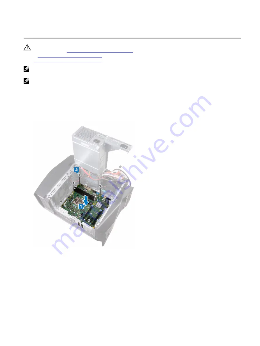
Replacing the system board
WARNING: Before working inside your computer, read the safety information that shipped with your computer and
follow the steps in
Before working inside your computer
. After working inside your computer, follow the instructions
After working inside your computer
. For more safety best practices, see the Regulatory Compliance home page at
www.dell.com/regulatory_compliance
NOTE: Your computer’s Service Tag is stored in the system board. You must enter the Service Tag in the BIOS setup
program after you replace the system board.
NOTE: Replacing the system board removes any changes you have made to the BIOS using the BIOS setup program.
You must make the appropriate changes again after you replace the system board.
Procedure
1
Align the system-board assembly with the slots on the chassis and place the system-board assembly in position.
2 Slide the system-board assembly to engage the latches that secure it to the chassis.
3 Replace the eight screws (#6-32 X 1/4") that secure the system-board assembly to the chassis.
4 Route and connect the front-chassis fan cable to the system board.
5 Route and connect the system-board power cable to the system board.
6 Route and connect the top-chassis fan cable to the system board.
7 Route and connect the processor power cable to the system board.
8 Route and connect the graphics-card power cable to the system board.
9 Route and connect the LED controller cable to the system board.
10 Route and connect the front panel audio cable to the system board.
11 Route and connect the hard drive data cable to the system board.
12 Route and connect the optical drive data cable to the system board.
101
Summary of Contents for Alienware Aurora R8
Page 23: ...3 Lift the right side cover off the chassis 23 ...
Page 25: ...3 Rotate the right side cover towards the chassis until it snaps into place 25 ...
Page 28: ...7 Lift the top cover from the top bezel 8 You are left with top bezel and top cover 28 ...
Page 31: ...Post requisites 1 Replace the right side cover 2 Replace the left side cover 31 ...
Page 33: ...4 Lift the bottom cover from the chassis 5 Turn the computer back to the upright position 33 ...
Page 48: ...12 Lift the power supply unit along with the cables off the chassis 48 ...
Page 77: ...4 Pry the antenna off the chassis 77 ...
Page 85: ...6 Lift the top chassis fan off the top chassis fan bracket 85 ...


