background image

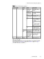
Table 2 SP status LEDs descriptions (continued)

Location

LED

Color

State

Description

Blue

Blinking once
every four
seconds (.25 Hz)

Operating system is
booting

Blinking once
every second (1
Hz)

Operating system driver
is starting

Blinking four times
every second (4
Hz)

Operating system
caching driver is starting

On

SP is not initialized. A
management IP address
is assigned.

Note

Once license accepted,
the SP fault LED turns
off.

Off

All operating system
software has booted and
SP is ready for I/O.

Amber and
blue

Alternating at one
second intervals

SP is in Service mode.

Intervals of amber
for one second
then immediately
blue for three
seconds

System not initialized and
no management IP
address assigned.

4

Ethernet I/O

Green

On

Ethernet link active

DPE front status LEDs
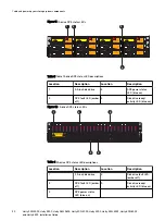
Verify that the storage system is up and running without error using the front facing
physical indicators on the 

Figure 11

 on page 30 and 

Table 3 

 on page 30 or 

Figure

12

 on page 30 and 

Table 4 

 on page 30.

Cable and power up your storage system components

Verify status LEDs


29

Summary of Contents for Unity 300

Page 1: ...Dell EMC Unity Family Unity 300 300F Unity 350F Unity 380 380F Unity 400 400F Unity 450F Unity 500 500F Unity 600 600F and Unity 650F Installation Guide P N 302 002 562 REV 05...

Page 2: ...Y DISCLAIMS IMPLIED WARRANTIES OF MERCHANTABILITY OR FITNESS FOR A PARTICULAR PURPOSE USE COPYING AND DISTRIBUTION OF ANY DELL SOFTWARE DESCRIBED IN THIS PUBLICATION REQUIRES AN APPLICABLE SOFTWARE LI...

Page 3: ...the network 26 DPE power up 26 Verify status LEDs 28 Installing the front bezel 31 Set up a management interface connection 33 Connect a Windows based computer to your storage system 34 Automatically...

Page 4: ...ptional DAE to extend back end bus 0 57 Cabling the DPE SAS module ports to create back end buses 2 through 5 58 Cabling an expansion DAE to an existing DAE to extend a back end bus 62 Connecting powe...

Page 5: ...at https Support EMC com After logging in locate the appropriate Support by Product page Technical support For technical support and service requests go to Online Support at https Support EMC com Aft...

Page 6: ...ons of this document might be released Check to ensure that you are using the latest version of this document Related documentation The following Unity system documents provide additional information...

Page 7: ...ion as well as the site requirements for the system l Before you begin 8 l Installation workflow including optional DAEs 8 l Site and equipment preparation 9 l Hardware acclimation times 10 l Avoiding...

Page 8: ...he storage system c Rack and install the storage system d Cable the system components e Power up the system components f Use the Connection Utility CU to discover and configure the system management I...

Page 9: ...tion on same LAN subnet as your storage system recommended n Web browser Internet Explorer Mozilla Firefox Google Chrome Note Refer to the Unity Support Matrix on the support website for compatibility...

Page 10: ...words for system users admin and service n If you are setting up the system on a network with DHCP servers DNS servers and Dynamic DNS services you need System serial number Domain information Hardwar...

Page 11: ...m on or in that system or component Do not exceed the shipping and storage temperature gradient of 45 F hr 25 C hr l Do NOT apply power to the system for at least the number of hours specified in Tabl...

Page 12: ...e possibility of an electrostatic discharge by ensuring that your body and the subassembly are at the same electrostatic potential NOTICE These precautions are not a substitute for the use of an ESD k...

Page 13: ...CHAPTER 2 Unpack your system Unpack the system components Verify that you have everything that you need to assemble and cable the system l Unpack the disk processor enclosure 14 Unpack your system 13...

Page 14: ...e slots Front view 25 2 5 drive slots 24 0 Will Make the Array Unusable Caution Array Software on drives 0 3 Removing or relocating them or Front view 12 3 5 drive slots 0 SAS12Gb SAS12Gb SAS12Gb SAS1...

Page 15: ...Component Bezel for disk processor enclosure 1 with key Unpack your system Verifying shipping package contents 15...

Page 16: ...Unpack your system 16 Unity 300 300F Unity 350F Unity 380 380F Unity 400 400F Unity 450F Unity 500 500F Unity 600 600F and Unity 650F Installation Guide...

Page 17: ...cables leave 1U of open space at the bottom of the cabinet when installing the DPE Also if all 40U of space in a single rack would be used use two racks instead and leave 1U of open space at the botto...

Page 18: ...s located on the top edge near the right side see Figure 1 on page 18 Figure 1 PSNT location on DPE with 12 drive slots PROD ID SN FNM01234567891 PN 123 456 789 OBERON PROD ID SN FNM01234567891 PN 123...

Page 19: ...nity Quick Start Installation Video at http bit ly unityinfohub Installing the rails in the cabinet Note The snap in rails are dedicated left and right and cannot be interchanged Procedure 1 First ori...

Page 20: ...secure the rails in place using one M5 screw on each rail Figure 4 Installing the M5 Screw 5 Working from the front of the cabinet align the adaptor with the mounting hole on the front of the rack as...

Page 21: ...mounting holes release the spring clip so it holds the rail in place CAUTION Ensure the spring clip is securely attached to the channel It may be necessary to push in on the clip to assist in snapping...

Page 22: ...der Besch digung des Ger tes bitte das Geh use nicht ohne die Hilfe einer zweiten Person anheben und einbauen Il contenitore pesante e dev essere installato nel rack da due persone Per evitare danni p...

Page 23: ...ure to the front vertical channels of the cabinet using four screws two per side by installing all four screws and then tightening them Figure 7 Securing enclosure to the front of the cabinet Install...

Page 24: ...Install your storage system components into a rack 24 Unity 300 300F Unity 350F Unity 380 380F Unity 400 400F Unity 450F Unity 500 500F Unity 600 600F and Unity 650F Installation Guide...

Page 25: ...section to connect the storage system components to the network and redundant power sources l Attach the storage processors to the network 26 l DPE power up 26 l Verify status LEDs 28 l Installing the...

Page 26: ...us step are required at this time Note Additional information about the ports and cabling is in the Hardware Information Guide available on the Unity Info Hub at http bit ly unityinfohub or on EMC Onl...

Page 27: ...end of the power cables into the PDU Connect the power supply for SP A shown as cable 1 in Figure 9 on page 27 to PDU A Connect the power supply for SP B shown as cable 2 in to PDU B 6 Bundle and secu...

Page 28: ...u continue DPE rear status LEDs Verify that the storage system is up and running without error using the rear facing physical indicators on the storage processor as shown in Figure 10 on page 28 and T...

Page 29: ...Off All operating system software has booted and SP is ready for I O Amber and blue Alternating at one second intervals SP is in Service mode Intervals of amber for one second then immediately blue fo...

Page 30: ...isk drive 3 DPE power status LED blue on 2 DPE fault LED amber off 4 Disk drive ready activity LED blue on Figure 12 25 drive DPE status LEDs Will Make the Array Unusable Caution Array Software on dri...

Page 31: ...remove the plastic protective strip from the front of the bezel 2 Align the bezel with the enclosure 3 Gently push the bezel into place on the cabinet until it latches 4 If the bezel has a lock inser...

Page 32: ...Cable and power up your storage system components 32 Unity 300 300F Unity 350F Unity 380 380F Unity 400 400F Unity 450F Unity 500 500F Unity 600 600F and Unity 650F Installation Guide...

Page 33: ...its management interface before you can register license or configure it l Connect a Windows based computer to your storage system 34 l Automatically assigning a dynamic storage system management por...

Page 34: ...e storage system in a network that supports DHCP or you would rather manually assign a static IP address you must install and run the Connection Utility on the Windows based computer Dynamic IP addres...

Page 35: ...th your system for example FNM00131800283 It is also on the PSNT tag on the front of the DPE dns_zone Network DNS zone on which the storage system is located for example mylab emc com Based on the exa...

Page 36: ...the displayed language based on the settings of the computer To change the language displayed in the Connection Utility select the language from the list under Change language Run the Connection Util...

Page 37: ...elect the system you want to configure and then click Next Note If you do not see the system listed on the screen try clicking Discover to restart the discovery process If the problem persists refer t...

Page 38: ...line Help for more information on configuring and start using your system Post requisites Upgrade the system Ensure that you upgrade the system to the latest operating environment and update the drive...

Page 39: ...CHAPTER 6 Unpack your DAE Unpack the DAE components Verify that you have everything that you need to assemble and cable the DAE l Unpack the optional disk array enclosures 40 Unpack your DAE 39...

Page 40: ...ounting screws 15 drive DAE container contents Verifying shipping package contents Confirm that you received all necessary equipment needed to install the new 15 drive DAE Verify that you received the...

Page 41: ...r 1 meter cables or to DPE 2 meter cables 2 25 drive DAE container contents Verifying shipping package contents Confirm that you received all necessary equipment needed to install the new 25 drive DAE...

Page 42: ...enclosure with key 1 mini SAS HD cables either 1 meter or 2 meter copper that connect disk array enclosures to each other 1 meter cables or to DPE 2 meter cables 2 Unpack your DAE 42 Unity 300 300F U...

Page 43: ...r cables leave 1U of open space at the bottom of the cabinet when installing the DPE Also if all 40U of space in a single rack would be used use two racks instead and leave 1U of open space at the bot...

Page 44: ...e that the rails are installed in the appropriate 2U space Procedure 1 From the rear of the cabinet insert the two key tabs into the holes of the 2U space on the rear cabinet channel Figure 14 Key tab...

Page 45: ...clip is forward of the front cabinet channel and the adaptor is in the mounting holes release the spring clip so it holds the rail in place CAUTION Ensure the spring clip is securely attached to the...

Page 46: ...dure 1 With help from another person lift the enclosure and from the front of the cabinet rack slide the enclosure onto the rails Figure 18 Sliding the enclosure onto the rails CL5845 2 Once the enclo...

Page 47: ...the adapters into the holes on the rear rack channel with the rail extended as shown in Figure 20 on page 48 3 Push the rail into the rear mounting holes until the spring clips snap into place on the...

Page 48: ...l from front to back and left to right Ensure you are using the same unit markers from the front of the cabinet to the rear of the cabinet 6 Push in on the spring clip while pulling the rail forward W...

Page 49: ...ist schwer und sollte nur von zwei Personen in einem Rack installiert werden Zur Vermeidung von k rperlichen Verletzungen und oder der Besch digung des Ger tes bitte das Geh use nicht ohne die Hilfe e...

Page 50: ...23 Sliding the enclosure onto the rails When the enclosure slides to the back of the cabinet the rear tabs on the rails insert into the notches in the rear of the enclosure The tabs secure and support...

Page 51: ...Figure 25 Securing the front of the enclosure Install your DAE components into a rack Install 25 drive DAE 51...

Page 52: ...Install your DAE components into a rack 52 Unity 300 300F Unity 350F Unity 380 380F Unity 400 400F Unity 450F Unity 500 500F Unity 600 600F and Unity 650F Installation Guide...

Page 53: ...our storage system to optional DAEs and to connect the DAE components to redundant power sources l Cabling the DPE to a DAE 54 l Cabling an expansion DAE to an existing DAE to extend a back end bus 62...

Page 54: ...the DPE are labeled 0 and 1 Mini SAS HD port 0 is connected internally to the SAS expander that connects the drives on the front of the DPE The DPE and its front facing drives begin the first back en...

Page 55: ...ted in different racks Cables are shipped without labels attached The cables and ports are not colored l Locate the sheet of cable labels provided Orient the cable connectors as described in the proce...

Page 56: ...g details Label part number Label Port Label part number Label Port 046 001 562 SP A SAS 1 SP A SAS 1 SP A SAS 1 SP A SAS 1 046 001 562_xx SP A SAS 1 046 021 012 LCC A PORT A 046 021 012_xx LCC A PORT...

Page 57: ...er to the address of this enclosure as BE0 EA1 0_1 Use the following illustration to complete this cabling task Figure 27 Example DPE to 15 drive DAE AC DC 1 GbE AC DC 1 GbE 4 5 2 3 MAC 1 4 5 4 5 4 5...

Page 58: ...b Connect port 0 on SP B in the top slot in the DPE to port A on the link control card LCC B at the top of the DAE 2 Cabling the DPE SAS module ports to create back end buses 2 through 5 Where support...

Page 59: ...port A l 2_0 side B black SP B B0 port 0 to DAE w LCC B port A l 3_0 side A green SP A B0 port 1 to DAE x LCC A port A l 3_0 side B green SP B B0 port 1 to DAE x LCC B port A l 4_0 side A brown SP A...

Page 60: ...0 PORT 1 046 005 718_xx SP B B0 PORT 1 SP B B0 PORT 1 SP B B0 PORT 1 SP B B0 PORT 1 046 021 019 LCC B Port A 046 021 019_xx LCC B Port A LCC B Port A LCC B Port A LCC B Port A 046 005 935 SP A A0 PORT...

Page 61: ...n the top slot of the DPE to port A on the link control card B LCC B at the top of the DAE Example 1 Connect the DAE to the DPE SP slot 0 port 0 to create back end bus 2 BE2 Connect the DAE to the DPE...

Page 62: ...0 SP B B0 PORT 0 046 021 017 LCC B Port A 046 021 017_xx LCC B Port A LCC B Port A LCC B Port A LCC B Port A 2 Connect slot 0 port 0 on SP A in the bottom slot in the DPE to port A on the link contro...

Page 63: ...range blue lack green brown or cyan shown here Typically DAEs connect to other DAEs using 1 meter cables Expansion port cable labeling details Primary port cable labeling details Label part number Lab...

Page 64: ...E2 LCC A Port A 046 004 465 B BE2 046 004 465_xx B BE2 B BE2 B BE2 LCC B Port B 046 004 465 B BE2 046 004 465_xx B BE2 B BE2 B BE2 LCC B Port A 046 004 458 A BE3 046 004 458_xx A BE3 A BE3 A BE3 LCC A...

Page 65: ...he mini SAS HD to mini SAS HD cables and use those cables to extend the bus For more information about cabling additional DAEs see the associated Hardware Information Guide a Connect port B on the lin...

Page 66: ...wer to the each DAE as follows a Connect the power cable for LCC A to PDU A b Connect the power cable for LCC B to PDU B The enclosures power up immediately once the cable is connected 5 Bundle and se...

Page 67: ...ration Worksheet This appendix contains a worksheet to collect and record information and to use as a guide to start setting up your storage system Topics include l Configuration worksheet 68 Configur...

Page 68: ...r the following information related to your Online Support account Item Value Online Support account l Go to support emc com to create your Online Support account l Your username and password will be...

Page 69: ...ard walks you through the initial set up of Unisphere and prepares the system for use The first time the wizard launches you will need to access the End User License Agreement EULA and install Unisphe...

Page 70: ...Enter your EMC Online Support username and password Customer Information Enter your customer contact information including name email and office phone number EMC Support will use this information to g...

Reviews: