Steps
1
Using a Torx #T30 screwdriver, loosen the screws on the heat sink in the order below:
a Loosen the first screw three turns.
b Loosen the second screw completely.
c Return to the first screw and loosen it completely.
NOTE:
It is normal for the heat sink to slip off the blue retention clips when the screws are partially loosened, continue
to loosen the screw(s).
2
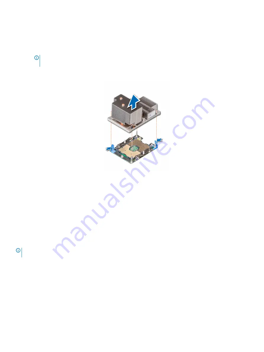
Pushing both blue retention clips simultaneously, lift the processor and heat sink module (PHM) out of the system.
3
Set the PHM aside with the processor side facing up.
Figure 58. Removing a processor and heat sink module (2U)
Next step
Install the processor and heat sink module
Removing the processor from the processor and heat sink
module
Prerequisites
NOTE:
Only remove the processor from the processor and heat sink module if you are replacing the processor or heat sink. This
procedure is not required when replacing a system board.
1
Follow the safety guidelines listed in
2
Follow the procedure listed in
Before working inside your system
.
3
Remove the processor and heat sink module
Steps
1
Place the heat sink with the processor side facing up.
2
Insert a flat blade screwdriver into the release slot marked with a yellow label. Twist (do not pry) the screwdriver to break the thermal
paste seal.
3
Push the retaining clips on the processor bracket to unlock the bracket from the heat sink.
110
Installing and removing system components
Summary of Contents for PowerEdge R740
Page 9: ...Figure 1 Supported configurations PowerEdge R740 system overview 9 ...
Page 28: ...Figure 22 NVDIMM battery and mid tray hard drives 28 PowerEdge R740 system overview ...
Page 141: ...Figure 94 Securing GPU 1 Installing and removing system components 141 ...
Page 142: ...Figure 95 Installing GPU 2 and 3 142 Installing and removing system components ...


