background image

Figure 4 Removing a disk

CL4583

4. Place the disk on a static-free surface.

5. Remove and store the ESD wristband.
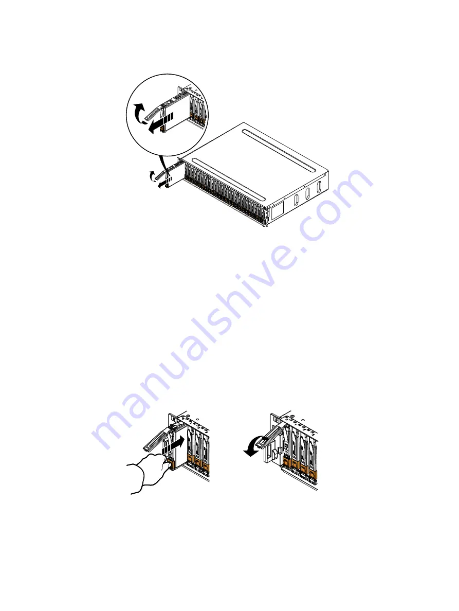
Installing a disk

Procedure

1. Attach an ESD wristband to your wrist and the enclosure in which you are installing the disk.

2. Align the disk with the guides in the slot.

3. With the disk carrier latch fully open, gently push the disk into the slot.

The latch begins to rotate downward when its tabs meet the enclosure.

4. Push on the orange latch tab until the disk is seated in the slot.

5. Push the handle down to engage the latch.

Figure 5 Installing a disk

SAS

300GB

10k

SAS

300GB

10k

CL4720

6. Remove and store the ESD wristband.

Installing the front bezel

Procedure

1. Align the bezel with the enclosure.

FRU Removal and Replacement

20

Dell EMC FS25 SSD Shelf Guide Field Replacement Unit Guide

Summary of Contents for FS25

Page 1: ...Dell EMC FS25 SSD Shelf Guide Version 7 0 Field Replacement Unit Guide Rev 01 September 2019 ...

Page 2: ...SPECIFICALLY DISCLAIMS IMPLIED WARRANTIES OF MERCHANTABILITY OR FITNESS FOR A PARTICULAR PURPOSE USE COPYING AND DISTRIBUTION OF ANY DELL SOFTWARE DESCRIBED IN THIS PUBLICATION REQUIRES AN APPLICABLE SOFTWARE LICENSE Dell Technologies Dell EMC Dell EMC and other trademarks are trademarks of Dell Inc or its subsidiaries Other trademarks may be the property of their respective owners Published in th...

Page 3: ...ent 25 Removing a faulted power cooling module 25 Installing a replacement power cooling module 27 Complete the procedure 29 Replacing a 25 Slot Disk Array Enclosure 31 Identify the failed drive 32 Disconnect cables 33 Opening the console 34 Removing the front bezel 35 Removing the DAE from the cabinet 35 Installing the empty replacement DAE5S on the rails 36 Transferring components from the fault...

Page 4: ...Installing the front bezel 47 Closing the console 48 Verify the operation of the new disk drive 48 Contents 4 Dell EMC FS25 SSD Shelf Guide Field Replacement Unit Guide ...

Page 5: ...bezel 35 Removing the screws that secure the enclosure to the front of the cabinet 36 Sliding the enclosure out of the cabinet 36 Sliding the enclosure onto the rails 37 Rail tabs securing the rear of the enclosure 37 Securing the front of the enclosure 38 Removing an AC power cooling module 39 Installing a power cooling module 40 Removing an LCC 41 Installing an LCC 42 Removing a disk 43 Installi...

Page 6: ...Figures 6 Dell EMC FS25 SSD Shelf Guide Field Replacement Unit Guide ...

Page 7: ...Document revision history 11 Standard touch point colors 17 Status lights 32 1 2 3 TABLES Dell EMC FS25 SSD Shelf Guide Field Replacement Unit Guide 7 ...

Page 8: ...Tables 8 Dell EMC FS25 SSD Shelf Guide Field Replacement Unit Guide ...

Page 9: ...or each of the supported platforms for example DD9500 and DD9800 l System specific safety and regulatory information Special Notice Conventions Used in this Document The following conventions for special notices are used WARNING Indicates a hazardous situation which if not avoided could result in death or serious injury CAUTION Indicates a hazardous situation which if not avoided could result in m...

Page 10: ... the user must specify such as x or y or z Ellipses indicate nonessential information that is omitted from the example Technical support To resolve issues with Dell EMC products contact your contracted support provider or go to https support emc com Your comments Your suggestions help us continue to improve the accuracy organization and overall quality of the user publications Send your opinions o...

Page 11: ...Revision history Table 1 Document revision history Revision Date Description 01 September 2019 Initial publication Dell EMC FS25 SSD Shelf Guide Field Replacement Unit Guide 11 ...

Page 12: ...Revision history 12 Dell EMC FS25 SSD Shelf Guide Field Replacement Unit Guide ...

Page 13: ...e following topics are contained in this chapter l Common procedures 14 l Disk replacement 17 l LCC replacement 21 l Power cooling module replacement 25 l Complete the procedure 29 Dell EMC FS25 SSD Shelf Guide Field Replacement Unit Guide 13 ...

Page 14: ...ove replacement or upgrade units from their antistatic packaging until you are ready to install them l Before you begin service gather together the ESD kit and all other materials you need l Once servicing begins avoid moving away from the work site otherwise you may build up an electrostatic charge l Use ESD anti static gloves or an ESD wristband with strap If using an ESD wristband with a strap ...

Page 15: ... the unpackaged system or component to reside in the operating environment for up to 16 hours in order to thermally stabilize and prevent condensation Transit storage environment Operating environment temperature Acclimation time Temperature Humidity Nominal 68 72 F 20 22 C Nominal 40 55 RH Nominal 68 72 F 20 22 C 40 55 RH 0 1 hour Cold 68 F 20 C Dry 30 RH 86 F 30 C 4 hours Cold 68 F 20 C Damp 30 ...

Page 16: ... bag and the specially designed shipping container in which you received it Use the antistatic bag and special shipping container when you need to return the replaceable unit l Replaceable units must acclimate to the operating environment before applying power This requires the unpackaged component to reside in the operating environment for up to 16 hours in order to thermally stabilize and preven...

Page 17: ... remains powered up on Note Some tasks may require additional steps Blue This color indicates that a shutdown of the system or component is required before you can perform the task such as removing a component with a blue lever Disk replacement This section describes how to replace a disk Opening the console About this task The console is a protruding plastic banner on the front of the cabinet wit...

Page 18: ...ed up Remove it only to replace or add a disk Procedure 1 If the bezel has a lock insert the key that shipped with your enclosure into the lock and turn the key to unlock the bezel 2 Press the two latch buttons on the bezel surface to release the bezel from the cabinet 3 Pull the bezel off the cabinet and put it on a clean static free surface FRU Removal and Replacement 18 Dell EMC FS25 SSD Shelf ...

Page 19: ...elease button to release the disk s latch 3 Do one of the following l If the disk s fault LED is on steadily slowly pull the disk about 1 inch 3 centimeters from its slot and wait 30 seconds for the disk to stop spinning before pulling the disk completely out of the slot l If the disk s fault LED light is off or mostly off slowly pull the disk completely out of the slot FRU Removal and Replacement...

Page 20: ...ier latch fully open gently push the disk into the slot The latch begins to rotate downward when its tabs meet the enclosure 4 Push on the orange latch tab until the disk is seated in the slot 5 Push the handle down to engage the latch Figure 5 Installing a disk SAS 300G B 10k SA S 300G B 10k CL4720 6 Remove and store the ESD wristband Installing the front bezel Procedure 1 Align the bezel with th...

Page 21: ...th the part you added or replaced close the console using the procedure that follows Procedure 1 Grasp the free side of the console and swing the console to the right to close it 2 Gently push on the console until it is closed LCC replacement This section describes how to replace an LCC Removing a faulted LCC Before you begin Identify the faulted LCC by it amber fault LED FRU Removal and Replaceme...

Page 22: ...an ESD wristband to your wrist and the enclosure 2 Remove each cable connected to the LCC by gently pulling the connector latches to release the cable from the connector Note where the cables connect to the LCC because you will reconnect them later Figure 8 Disconnecting an LCC cable CL5983 3 Remove the LCC FRU Removal and Replacement 22 Dell EMC FS25 SSD Shelf Guide Field Replacement Unit Guide ...

Page 23: ...it a Locate the orange handle buttons on the LCC handles b Press the orange handle buttons to release the LCC pull the latches outward and remove the LCC from its slot Figure 9 Removing an LCC CL5984 2 1 4 Place the LCC on a clean static free surface FRU Removal and Replacement Dell EMC FS25 SSD Shelf Guide Field Replacement Unit Guide 23 ...

Page 24: ... Align the LCC with the enclosure opening and gently push the LCC straight into the enclosure being sure the LCC is completely seated in the enclosure Figure 10 Installing an LCC CL5985 2 1 4 Press the latches to secure the LCC 5 Reconnect each cable to the port from which it was removed FRU Removal and Replacement 24 Dell EMC FS25 SSD Shelf Guide Field Replacement Unit Guide ...

Page 25: ...time out and the disks will spin down two minutes after a power cooling module is removed from the enclosure While the system can continue operating on a single power supply the loss of a module s two blowers causes the DAE to power down unless you replace the module within two minutes When replacing both cooling modules ensure the green light on one module has been steadily on for at least 5 seco...

Page 26: ...ure 14 Unplugging the power cord from a DC power supply cooling module Spring Release CL5060 4 Remove the power cooling module as follows a Press the orange handle button to release the module b Pull the latch outward and remove the power cooling module from its slot CAUTION To protect a running system from overheating the enclosure will power down unless you replace the power cooling module withi...

Page 27: ...tall the power cooling module in the enclosure within two minutes a Gently insert the power cooling module into the enclosure being sure that the module is completely seated b Press the latch in to secure the power cooling module FRU Removal and Replacement Dell EMC FS25 SSD Shelf Guide Field Replacement Unit Guide 27 ...

Page 28: ...ing module a Plug the power cord into the power cooling module b Secure the cord with the retention bail at the connector The bail prevents the power cord from pulling out of the connector FRU Removal and Replacement 28 Dell EMC FS25 SSD Shelf Guide Field Replacement Unit Guide ...

Page 29: ...Return the failed or replaced part s to Dell EMC Reuse the packaging from the new part s and use the included prepaid waybill for shipping Reference the RMA number on the outside of the package 2 Send an autosupport report from the system by entering the autosupport send command FRU Removal and Replacement Dell EMC FS25 SSD Shelf Guide Field Replacement Unit Guide 29 ...

Page 30: ...FRU Removal and Replacement 30 Dell EMC FS25 SSD Shelf Guide Field Replacement Unit Guide ...

Page 31: ...e front bezel 35 l Removing the DAE from the cabinet 35 l Installing the empty replacement DAE5S on the rails 36 l Transferring components from the faulted DAE to the replacement DAE 38 l Attaching an AC power cord 45 l Verifying the status of the replacement DAE5S 45 l Connect the SAS cables 47 l Installing the front bezel 47 l Closing the console 48 l Verify the operation of the new disk drive 4...

Page 32: ...ity the ready state l Slow blinking when the drive is spinning and handling I O activity Disk fault 1 per disk module Amber On when the disk module is faulty or as an indication to replace the drive 2 Log in as a sysadmin user 3 Enter the alerts show current command to display messages indicating disk drive failure Sample output for this command is shown alerts show current Id Post Time Severity C...

Page 33: ...e 1 Remove each cable connected to the LCCs by gently pulling the connector latches to release the cable from the connector Label each cable so you can easily identify where to reconnect Figure 18 Disconnect LCC cables CL5983 2 On both power supplies release the cable retention bail 3 Disconnect both power cables Replacing a 25 Slot Disk Array Enclosure Dell EMC FS25 SSD Shelf Guide Field Replacem...

Page 34: ...the product badge If the console is covering the front of the to which you need access open the console using the steps that follow Refer to Figure 20 on page 34 Procedure 1 Grasp the right side of the console 2 Pull the console to swing it open Figure 20 Opening the console 2 1 CL4699 Replacing a 25 Slot Disk Array Enclosure 34 Dell EMC FS25 SSD Shelf Guide Field Replacement Unit Guide ...

Page 35: ...emove components such as disks LCCs or power cooling modules from the faulted DAE before removing the chassis from the cabinet Doing so greatly increases the risk of returning a component to the wrong slot in the replacement chassis which can result in data loss CAUTION The enclosure is heavy and should be installed into or removed from a rack by two people To avoid personal injury and or damage t...

Page 36: ...compartimento no debe levantarse ni instalarse en el bastidor sin la ayuda de un elevador mecánico o de otra persona Procedure 1 Remove the four screws two per side that secure the front of the enclosure to the front vertical channels of the cabinet and save the screws Figure 22 on page 36 Figure 22 Removing the screws that secure the enclosure to the front of the cabinet CL4727 2 With help from a...

Page 37: ...closure The tabs secure and support the rear of the enclosure Figure 25 Rail tabs securing the rear of the enclosure CL5994 2 Secure the front of the enclosure to the front vertical channels with four screws two per side but do not tighten the screws until they are all in place Replacing a 25 Slot Disk Array Enclosure Dell EMC FS25 SSD Shelf Guide Field Replacement Unit Guide 37 ...

Page 38: ...ys move a component from position A faulted to position A replacement or B to B do not move A to B or B to A n Move components from position A of the faulted DAE to position A of the replacement DAE n Move components from position B of the faulted DAE to position B of the replacement DAE l Transfer each disk and disk filler module to the SAME SLOT LOCATION that it occupied in faulted DAE Removing ...

Page 39: ... module Procedure 1 Gently insert the power cooling module into the enclosure being sure that the module is completely seated 2 Press the latch in to secure the power cooling module Replacing a 25 Slot Disk Array Enclosure Dell EMC FS25 SSD Shelf Guide Field Replacement Unit Guide 39 ...

Page 40: ... LCC comes completely out of the DAE chassis In addition to holding the latches be prepared to support the LCC to avoid dropping it Procedure 1 Locate the orange handle buttons on the LCC handles Replacing a 25 Slot Disk Array Enclosure 40 Dell EMC FS25 SSD Shelf Guide Field Replacement Unit Guide ...

Page 41: ...re 1 Pull out the latches on the LCC and make sure they stay in the open position 2 Align the LCC with the enclosure opening and gently push the LCC straight into the enclosure being sure the LCC is completely seated in the enclosure 3 Press the latches to secure the LCC Replacing a 25 Slot Disk Array Enclosure Dell EMC FS25 SSD Shelf Guide Field Replacement Unit Guide 41 ...

Page 42: ...Make sure to transfer the disks and any disk filler modules to the same slots in the replacement enclosure that they occupied in the faulted enclosure Installing disks out of their original order results in data unavailability and possible data loss Removing a disk About this task Refer to Figure 31 on page 43 while performing the procedure that follows Replacing a 25 Slot Disk Array Enclosure 42 ...

Page 43: ... on page 44 while performing the procedure that follows Procedure 1 Attach an ESD wristband to your wrist and the enclosure in which you are installing the disk 2 Align the disk with the guides in the slot 3 With the disk carrier latch fully open gently push the disk into the slot The latch begins to rotate downward when its tabs meet the enclosure 4 Push on the orange latch tab until the disk is ...

Page 44: ...module down and pull the disk filler module out of the slot Figure 33 Removing a disk filler module CL5278 1 2 Installing a disk filler module About this task Refer to Figure 34 on page 45 while performing the procedure that follows Procedure 1 Insert your finger into the cutout on the bottom of the disk filler module 2 With your thumb on the top of the disk filler module push the disk filler modu...

Page 45: ...tors on the power cooling modules 2 Attach the retention bail strain relief to the base of the power cords The retention bail prevents the power cord from pulling out of the connection Figure 35 Attaching power cords Verifying the status of the replacement DAE5S Procedure 1 Verify that both LCC power LEDs are lit Replacing a 25 Slot Disk Array Enclosure Dell EMC FS25 SSD Shelf Guide Field Replacem...

Page 46: ...l LCC fault LED one per LCC Figure 37 LCC fault LED CL5982 l Power cooling module fault LED one per module Figure 38 Power cooling module fault LED CL5987 l Disk fault LED one per disk Replacing a 25 Slot Disk Array Enclosure 46 Dell EMC FS25 SSD Shelf Guide Field Replacement Unit Guide ...

Page 47: ...ng decimal numbers Figure 40 Bus loop ID LED CL5993 LCC enclosure ID Bus loop ID Installing the front bezel Before you begin CAUTION If the protective plastic strip is present on the front of the bezel it must be removed before placing the system into operation Failure to remove the protective plastic strip will cause the system to overheat About this task Refer to Figure 41 on page 48 while perfo...

Page 48: ...e right to close it 2 Gently push on the console until it is closed Verify the operation of the new disk drive Procedure 1 Rescan all of the disks by entering the disk rescan command Note This command does not generate any output The amount of time it takes to complete depends on how many disks are attached 2 After the rescan completes enter the disk show state command to verify the state of all d...

Page 49: ...disk are in good state 3 After the rescan if the output of the disk show state command displays any disks in the Unkown Failed or Absent states run the disk unfail enclosure id disk id command to unfail the disk For example to unfail enclosure 2 disk 2 type disk unfail 2 2 Replacing a 25 Slot Disk Array Enclosure Dell EMC FS25 SSD Shelf Guide Field Replacement Unit Guide 49 ...

Page 50: ...Replacing a 25 Slot Disk Array Enclosure 50 Dell EMC FS25 SSD Shelf Guide Field Replacement Unit Guide ...

Reviews: