Deif SGC 120 User Manual Download Page 47

9. Modbus communication protocol

9.1 About the Modbus communication protocol

SGC 120/121 supports a custom protocol based on the standard Modbus over an RS-485 layer. operates in a slave mode and
responds to commands received from an external Modbus master.

9.2 Modbus connection details

The transmission mode used by SGC 120/121 is Modbus RTU (not Modbus ASCII). The byte format for communication is 1 start bit,
8 data bits, no parity bits and 1 stop bit, Cyclic Redundancy Check (CRC).

Precautions

Find the slave ID from the SMPS and configure the same ID in the controller.

Enable the controller in the configuration of the SMPS after hardware connections are made.

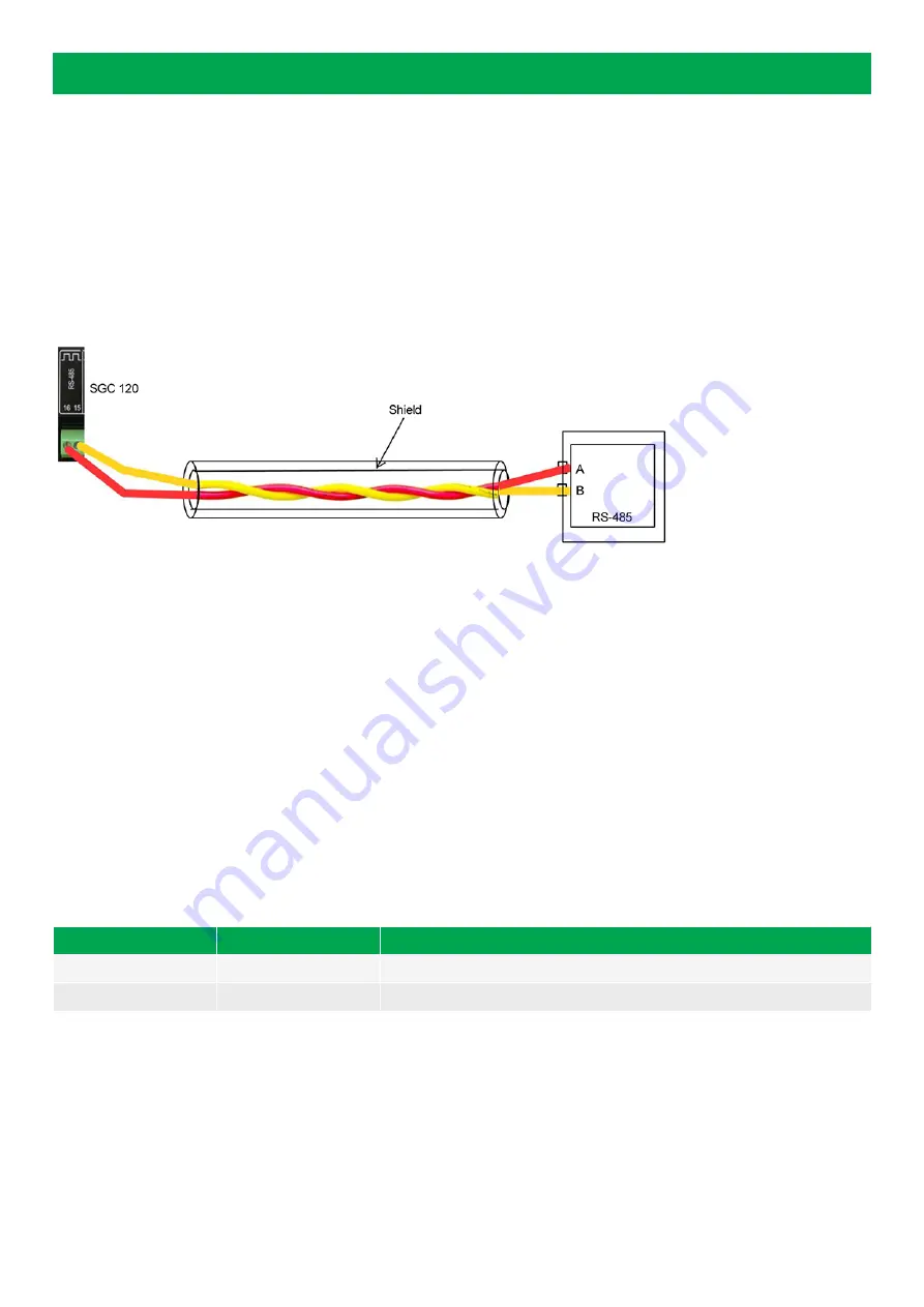
Connect the controller terminals 16 and 15 to the SMPS terminals A and B.

Use a two-core shielded cable for connection.

Use different colour wires for terminals 16 and 15 for easy detection and connection.

Route the wires properly ensuring they do not get short with any other wires.

Do not use multi strand wires for the connection.

9.3 Modbus functions

This genset controller operates as a Modbus slave that responds to certain commands (or functions, as defined by Modbus
standard) received from the Modbus master in appropriate format. Supported functions and respective command-response structure
is as shown below. If the command received from the Modbus master is other than the three functions mentioned below, an
exception message is generated.

Function code

Modbus name

Description

03 

Read holding register 

Reads one or more 16-bit registers from the slave device read/write location. 

16 

Write holding register 

Writes one or more 16-bit registers to the slave device. 

USER MANUAL 4189341226A UK 

Page 47 of 72

Summary of Contents for SGC 120

Page 1: ...User manual Single Genset Controller SGC 120 121 DEIF A S Frisenborgvej 33 DK 7800 Skive Tel 45 9614 9614 Fax 45 9614 9615 info deif com www deif com Document no 4189341226A...

Page 2: ...nputs used as digital inputs 12 3 9 Analogue voltage current input 12 3 10 Magnetic pick up MPU input 13 3 11 Digital outputs 13 3 12 Rotary actuator outputs SGC 121 only 13 3 13 D Charger alternator...

Page 3: ...1 Modbus communication settings 48 10 2 Register map function code 03 49 10 3 Register map function code 16 55 11 Engine communication SGC 120 only 11 1 Introduction to engine communication 56 11 2 D...

Page 4: ...the genset controller 1 2 Key functions Genset controller with configurable inputs Five digital inputs Four analogue inputs configurable as digital inputs Six digital outputs Auto Manual and Remote st...

Page 5: ...4 Passwords The controller is protected from set up changes with a four digit password There are two password levels Level Access Factory setting 1 Full access read and write 0123 2 Limited access rea...

Page 6: ...ters Programming mode Auto Stop Stops the engine and enters Manual mode Manual Auto Configuration Up Down Scrolls through the views parameters Manual Auto Up Down during Alarm view Acknowledges and cl...

Page 7: ...sible for the installation or the operation of the set must be contacted DEIF A S reserves the right to change any of the contents of this document without prior notice The English version of this doc...

Page 8: ...rings must be of appropriate size 2 3 In operation safety Before installing the controller ensure that all power voltage supplies are positively turned off at the source Disconnect the generator s bat...

Page 9: ...6 mm 5474274 5453499 2 Note Phoenix Phoenix Contact I Pvt Ltd 3 2 Power supply Category Specification Controller terminals 1 Ground 2 Battery or DC Supply voltage range Nominal voltage 12 24 V DC Oper...

Page 10: ...ables to the genset controller s phase L1 and neutral terminals 3 4 Genset current measurements Category Specifications Controller terminals 39 and 40 for phase L1 37 and 38 for phase L2 35 and 36 for...

Page 11: ...Controller overview Configurable parameters in the User manual for more details 3 7 Analogue resistive sensor inputs Category Specifications Controller terminals 24 Engine temperature 25 Fuel level s...

Page 12: ...eries 3 8 Analogue inputs used as digital inputs Analogue inputs can be used as digital inputs when wired as shown F1 8 28 V DC 3 9 Analogue voltage current input Category Specifications Controller te...

Page 13: ...ler s output terminals Genset and mains contactor latching relays should be compiled against 4 kVA surge as per IEC 61000 4 5 standard 3 12 Rotary actuator outputs SGC 121 only Category Specifications...

Page 14: ...s those for measuring lube oil pressure engine temperature and fuel level The electrical cable used for the connection should not be shared with any other electrical connection Such a wiring practice...

Page 15: ...in panel To mount the controller into the panel use the fixing clips provided along with the controller 1 Panel surface 2 Mounting clips a Insert the mounting clips into the slots on the controller b...

Page 16: ...430 4 DIG OUT B DC output B 5 DIG OUT C DC output C 6 DIG OUT D DC output D 7 D CHG ALT Input for charging alternator control 5441223 8 DIG OUT E DC output E 9 DIG OUT F DC output F 10 DIG IN A Input...

Page 17: ...ge input from Generator Neutral 5453499 28 GEN_V IN L3 Voltage input from Generator phase L3 29 GEN_V IN L2 Voltage input from Generator phase L2 30 GEN_V IN L1 Voltage input from Generator phase L1 3...

Page 18: ...CU DC DC D Input Input Sensor common Input Input Tacho High Low Data A Data B RS485 USB AC voltage Mains N L1 L2 L3 Digital inputs configurable In In In In In AC current CT AC voltage genset L1 s1 L1...

Page 19: ...Output Output Output Output G D B Sensor common Engine body NOTE Wiring diagrams are examples Use the application s wiring diagram during installation Genset and mains contactor latching relays should...

Page 20: ...lso be changed manually with the Up and Down buttons Engine status and operating mode Manual mode Auto mode Generator voltage 2 1 kVA Load power1 Load apparent power1 Load reactive power1 Generator po...

Page 21: ...controller is configured for a 3 phase genset 2 The display is only visible if the corresponding sensor is configured 3 The display is only visible if the event is enabled in the controller s configur...

Page 22: ...rough the digits with the Up and Down buttons Select a digit with the Start button 6 To leave the Configuration mode press and hold the Stop Config button 7 Until the configuration is saved the displa...

Page 23: ...Table 6 2 Display DISPLAY Level 2 Range Contrast CONTRAST 0 to 100 Power Save Mode POWER SAVE MODE Enable Disable Table 6 3 Communication RS485 COMM Level 2 Range Communication Mode COMM MODE None Mod...

Page 24: ...nt Day EVENT DAY Daily Runs every day Weekly Sunday to Saturday Monthly 1 to 28 Start Time START TIME 00 00 to 23 59 hour Duration GEN ON DURATION 00 hr 01 min to 99 hr 59 min Load Transfer LOAD TRANS...

Page 25: ...ivation DIG ACTIVATION Never From Engine Start From Monitoring On Always Digital Activation Delay DIG ACTIVATION DELAY 1 to 60 s ETS Circuit Fault Action OPEN CKT ALARM None Notification Warning Elect...

Page 26: ...Enable Disable FLS Fuel Theft Alarm Threshold FUEL LVL THRESH 1 to 100 per hour FLS Circuit Fault Action OPEN CKT ALARM None Notification Warning Electrical Trip Shutdown FLS Fuel Sensor Reference FU...

Page 27: ...ital input source selection in this document Name NAME Auxiliary Input I Digital Polarity DIG POLARITY Close to Activate Open to Activate Digital Action DIG ACTION None Notification Warning Electrical...

Page 28: ...to 60 s Manual Start Delay MANUAL START DELAY 0 to 300 s Auto Start Delay AUTO START DELAY 0 to 43200 s Table 6 13 General GENERAL TIMER Level 2 Range Safety Monitoring Delay SAFETY MONITOR DELAY 10 t...

Page 29: ...e Min Healthy Voltage MIN HEALTHY VOLT 50 to 350 V phase neutral Min Healthy Frequency MIN HEALTHY FREQ 10 to 75 Hz Phase Reversal Detection PHASE REVERSAL DETECT Enable Disable Phase Reversal Action...

Page 30: ...ency Warning Threshold UF WARNING THRESHOLD 11 0 to 60 0 Hz Over frequency Shutdown Enable OVER FREQ SHUTDOWN Enable Disable Over frequency Shutdown Threshold OF SHUTDOWN THRESH 26 0 to 75 0 Hz Over f...

Page 31: ...Delay UNBAL LOAD DELAY 1 to 600 s 6 2 8 Mains Table 6 19 Configuration MAINS CONFIG Level 2 Range Mains Monitoring MAINS MONITORING Enable Disable Mains AC System MAINS AC SYSTEM 1 phase 3 phase Phas...

Page 32: ...il Pressure Sensor DISCONN ON LOP SENS Enable Disable Monitor Pressure Sensor Before Crank MON LLOP BEF CRANK Enable Disable Pressure Sensor Monitoring Threshold DISCONN LOP SENS 0 5 to 10 0 bar Monit...

Page 33: ...ROSS OS THRESHOLD 100 to 200 Table 6 24 Battery Monitoring BATTERY MONITOR Level 2 Range Low Battery Voltage Action LOW VOLT ACTION None Notification Warning Electrical Trip Shutdown Low Battery Volta...

Page 34: ...00 C Table 6 27 Engine Control Unit ECU SGC 120 0nly Level 2 Range Engine Type None Generic J1939 Scania Volvo Iveco Deutz MVR MTU Cummins Measurements from the ECU Lube Oil Pressure Enable Disable Co...

Page 35: ...ectrical Trip Shutdown Activation Never From Enigine Start From Monitoring On Always Activation Delay 0 to 60 s Table 6 28 Lube Oil Pressure LOP Level 2 Range Low Level Shutdown Enable Disable Shutdow...

Page 36: ...DIRECTION Clockwise to Stop Anti clockwise to stop Governing Mode GOVERNING MODE Fixed Speed Variable Speed Table 6 32 Engine Start Strategy ENG START STRGY Level 2 Range Cranking Steps CRANKING STEPS...

Page 37: ...1000 Table 6 34 Engine EGov Config ENG EGOV CNFG Level 2 Range Target Speed TARGET SPEED 500 to 4000 RPM Proportional Gain Kp PROPORTIONAL GAIN 0 to 1000 Integral Gain Ki INTEGRAL GAIN 0 to 2000 Deri...

Page 38: ...ency Stop 8 Remote Start Stop 9 Simulate Start 10 Simulate Stop 11 Simulate Auto 12 Close Gen Open Mains Switch 13 Close Mains Open Gen Switch 14 Simulate Mains 15 V Belt Broken Switch 6 4 Digital out...

Page 39: ...ase OV Shutdown 31 L1 Phase UV Shutdown 32 L2 Phase OV Shutdown 33 L2 Phase UV Shutdown 34 L3 Phase OV Shutdown 35 L3 Phase UV Shutdown 36 Gen Over Current 37 High Engine Coolant Temp 38 Low Fuel LVL...

Page 40: ...No Output source 52 Maintenance Due 53 Stop Mode 54 Auto Mode 55 Manual Mode 56 Preheat Output USER MANUAL 4189341226A UK Page 40 of 72...

Page 41: ...up delay timer starts At the end of the Warm up delay the Load transfer delay starts and the genset latches Engine running hours increase while the genset runs The running hours stop increasing when...

Page 42: ...e start stop configuration simultaneously Exercise Mode Two scheduled sequences to start and stop the genset can be configured with SGC 120 121 Exercise mode occurs when the controller is in Auto mode...

Page 43: ...ed automatically The controller goes to Deep sleep mode when there is no user interaction for the preset Deep sleep mode delay The controller does not go to Deep sleep mode under the following conditi...

Page 44: ...e cooling timer begins after which the genset is stopped 3 Warning Warning alarms draw the operator s attention to an undesirable condition without affecting the genset s operation The genset cannot b...

Page 45: ...Emergency Stop Configured as digital input has triggered longer than preset or when an immediate shutdown is required Shutdown 12 Fail To Stop It is detected that genset is still running after sendin...

Page 46: ...t will shut down immediately without any delay Shutdown 28 Under Speed The engine speed has fallen below the preset RPM Shutdown 29 Extended Over Load Trip Indicates that there was 100 load on the gen...

Page 47: ...se a two core shielded cable for connection Use different colour wires for terminals 16 and 15 for easy detection and connection Route the wires properly ensuring they do not get short with any other...

Page 48: ...te low byte 6 Number of data bytes to follow n 7 Value at first register 6 n Value at last register 7 n 8 n Error check CRC Normal response from SGC 120 121 slave for Function 16 Byte Field Remarks 0...

Page 49: ...nit Interpretation Bits Sign 0 Protocol revision Unsigned 1 Generator L1 N voltage 0 1 V Unsigned 2 Generator L2 N voltage 0 1 V Unsigned 3 Generator L3 N voltage 0 1 V Unsigned 4 Generator L1 L2 volt...

Page 50: ...Load L3 var 0 1 kvar Unsigned 38 Load total var 0 1 kvar Unsigned 39 40 Generator cumulative energy 0 1 kWh Unsigned 41 42 Generator cumulative apparent energy 0 1 kVAh Unsigned 43 44 Generator cumula...

Page 51: ...ncy 5 16 8 16 Generator high frequency 1 16 4 16 68 Alarm 4 Generator high current 13 16 16 16 Generator overload 9 16 12 16 Unbalanced load 5 16 8 16 Emergency stop 1 16 4 16 69 Alarm 5 Charge altern...

Page 52: ...phase low volt 5 16 8 16 Gen L2 phase high volt 1 16 4 16 75 Alarm 11 Gen L3 phase low volt 13 16 16 16 Gen L3 phase high volt 9 16 12 16 DG phase rotation 5 16 8 16 Mains phase rotation 1 16 4 16 76...

Page 53: ...ut B 15 16 Digital input C 14 16 Digital input D 13 16 Digital input E 12 16 Digital input F 11 16 Digital input G 10 16 Digital input H 9 16 Digital input I 8 16 Digital output A 7 16 Digital output...

Page 54: ...6 DG fail to start True 1 False 0 6 16 Gen available True 1 False 0 5 16 Common shut down True 1 False 0 4 16 Common electric trip True 1 False 0 3 16 Common warning True 1 False 0 2 16 Common notific...

Page 55: ...he time stamp is 14 18 21 Thursday 02 04 2020 10 3 Register map function code 16 Register map function code 16 Register offset Description Note Bits Sign 0 DG mode change command SGC STOP KEY 0x01 SGC...

Page 56: ...tion value Other engines and controllers For engines and controllers not listed in this document contact DEIF 11 2 Default settings The SGC controller is delivered with a set of default settings for e...

Page 57: ...rom the engine ECU 3 Configure the settings for the ECU communication failure alarm 4 Configure the settings for the diagnostic lamps on the ECU Amber lamp Red lamp Malfunction lamp Protect lamp See t...

Page 58: ...s active alarms Alarm log DM2 shows historic alarms Scroll through the alarm list with the Up and Down buttons oc Shows how many times a specific alarm has occurred CLRALL Press ENTER to clear the ent...

Page 59: ...the expected source address when TSC1 SA is 1 default value You can configure the controller for a specific source address the range is 0 to 255 Ask the engine manufacturer to verify the TSC1 source...

Page 60: ...e controller Response to the commands is a part of the data that is broadcast Communication structure page 0 Register offset Value Scale factor Unit Bits Sign 0 Protocol revision Unsigned 1 Generator...

Page 61: ...V Unsigned Communication structure page 7 Register offset Value Scale factor Unit Bits Sign 21 Load L1 current 1 A Unsigned 22 Mains L2 frequency 1 Hz Unsigned 23 Mains L3 frequency 1 Hz Unsigned Com...

Page 62: ...1 kVAh Unsigned Communication structure page 15 Register offset Value Scale factor Unit Bits Sign 43 44 Generator cumulative reactive energy 0 1 kvarh Unsigned Communication structure page 16 Registe...

Page 63: ...rs Unsigned 63 Mains run min 1 min Unsigned Communication structure page 23 Register offset Value Scale factor Unit Bits Sign 64 Alarm 1 Low oil pressure E 0001 0001 W 0010 0010 S 0011 0011 3 16 16 16...

Page 64: ...nt E 0001 0001 N 0101 0101 W 0010 0010 E 0100 0100 S 0011 0011 13 16 16 16 Generator overload E 0001 0001 N 0101 0101 W 0010 0010 E 0100 0100 S 0011 0011 9 16 12 16 Unbalanced load E 0001 0001 N 0101...

Page 65: ...01 N 0101 0101 W 0010 0010 E 0100 0100 S 0011 0011 5 16 8 16 Reserved 1111 1 16 4 16 Communication structure page 25 Register offset Value Scale factor Unit Bits Sign 70 Alarm 7 Fuel theft 13 16 16 16...

Page 66: ...1 0011 5 16 8 16 Auxiliary input D E 0001 0001 N 0101 0101 W 0010 0010 E 0100 0100 S 0011 0011 1 16 4 16 72 Alarm 9 Auxiliary input E E 0001 0001 N 0101 0101 W 0010 0010 E 0100 0100 S 0011 0011 13 16...

Page 67: ...01 0001 W 0010 0010 S 0011 0011 13 16 16 16 Gen L3 phase high volt E 0001 0001 W 0010 0010 S 0011 0011 9 16 12 16 DG phase rotation E 0001 0001 N 0101 0101 W 0010 0010 E 0100 0100 S 0011 0011 5 16 8 1...

Page 68: ...0 14 16 Digital input D 1 0 13 16 Digital input E 1 0 12 16 Digital input F 1 0 11 16 Digital input G 1 0 10 16 Digital input H 1 0 9 16 Digital input I 1 0 8 16 Digital output A 1 0 7 16 Digital out...

Page 69: ...il to start True 1 False 0 6 16 Gen available True 1 False 0 5 16 Common shutdown True 1 False 0 4 16 Common electric trip True 1 False 0 3 16 Common warning True 1 False 0 2 16 Common notification Tr...

Page 70: ...CAN Command ID Description Command parameter each of 1 Bytes Bits Sign 1 Start Stop command 0x01 Start DG 0x02 Stop DG Command status is updated in status register Unsigned 2 Operating mode change co...

Page 71: ...in the controller and verify the respective threshold configuration The controller shows Charge Fail alarm To check if the controller s charging alternator terminal is working Disconnect the charging...

Page 72: ...s monitoring disabled and Site mode disabled Controller does not stop engine even when a Remote stop command is sent from an external device Check the wiring of the Remote stop signal to the controlle...

Reviews: