ZEN-LOG-MAN-16V03 (0930)
Copyright © 2016 Define Instruments
29
7.4 - Thermocouple input
Thermocouple types
B, E, J, K, N, R, S or
T type (see table below for ranges)
Cold junction compensation
14 to 140°F
(–10 to 60°C)
CJC drift
<0.02°C/°C typical for all inputs
Sensor open
Upscale
TC lead resistance
100Ω max
Input impedance
>500KΩ
Accuracy
0.1% of FSO ±1°C typical
The thermocouple
is one of the most
common tempera-
ture sensors used in
industry. It relies on
the Seebeck coefficient
between dissimilar
metals. The thermo-
couple type is selected
with reference to the
application tempera-
ture range and environment, with J and K
type being the most common.
Supported thermocouple types/ranges
B
32 to 3272°F
(0 to 1800°C)
E
-328 to 1292°F
(-200 to 700°C)
J
-328 to 1832°F
(-200 to 1000°C)
K
-328 to 2300°F
(-200 to 1260°C)
N
-328 to 2372°F
(-200 to 1300°C)
R
32 to 3092°F
(0 to 1700°C)
S
32 to 3092°F
(0 to 1700°C)
T
-328 to 752°F
(-200 to 400°C)
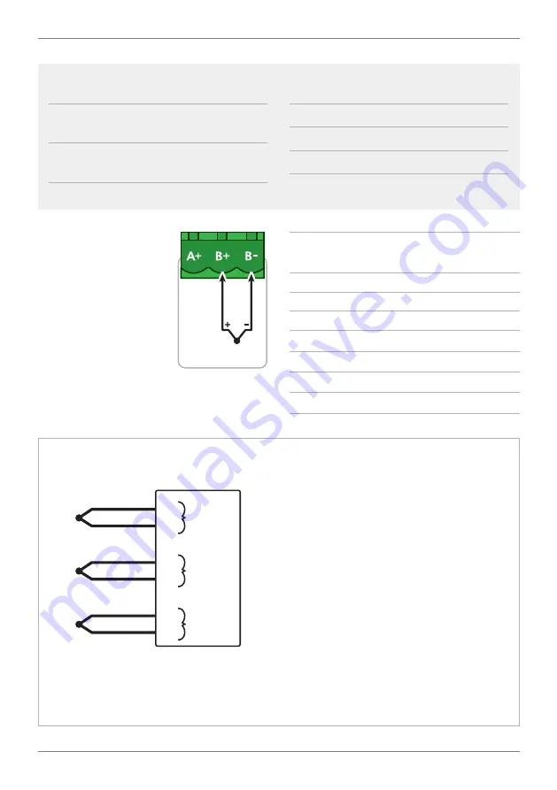
Thermocouple
Connection Example for
Thermocouple Inputs
T/C
T/C
T/C
Input
Channel
B+
B–
Input
Channel
B+
B–
Input
Channel
B+
B–
Note 1
All thermocouple inputs are iso-
lated from each other. There is no need to
buy expensive isolated thermocouples.
Note 2
For accurate thermocouple mea-
surements (especially at low tempera-
tures) the top cover must always be fitted.
Avoid drafts and temperature differences
across terminals. Once installation is com-
plete, close the cabinet door and allow
the cabinet to reach equilibrium. This may
take several hours. Place all thermocouple
probes into a calibrated thermal bath at
temperature of interest. Any offsets can
be zeroed out in the software.
Note 3
All thermocouples are referenced
to a combination of four CJC tempera-
ture sensors on the main Zen board. This
minimizes errors caused by the mounting
orientation of the Zen unit, and tempera-
ture differences in enclosures. However,
for high accuracy applications it is still


