5TE Operator’s Manual
5. Connecting Sensors
16
NOTE: The acceptable range of excitation voltages is from 3-15 VDC.
If you wish to read the 5TE with the Campbell Scientific Data Loggers,
you will need to power the sensors off of the switched 12V port.
If your 5TE is equipped with the standard 3.5mm plug, and
you wish to connect it to a non-Decagon datalogger, you have
two options. First, you can clip off the plug on the sensor
cable, strip and tin the wires, and wire it directly into the data-
logger. This has the advantage of creating a direct connection
with no chance of the sensor becoming un-plugged; however,
it then cannot be easily used in the future with a Decagon
readout unit or datalogger. The other option is to obtain an
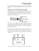
adapter cable from Decagon. The 3-wire sensor adapter cable
has a connector for the sensor jack on one end, and three
wires on the other end for connection to a datalogger (this
type of wire is often referred to as a “pigtail adapter”). Both
the stripped and tinned adapter cable wires have the same ter-
mination as seen above; the white wire is excitation, red is out-
put, and the bare wire is ground.
Logger Communications
When excitation voltage is applied, the 5TE makes a measur-
ment. Within about 50 ms of excitation three measurement
values are transmitted to the data logger as a serial stream of
ASCII characters. The serial out is 1200 baud asynchronous
with 8 data bits, no parity, and one stop bit. The voltage levels
are 0-3.6V and the logic levels are TTL (active low). The
power must be removed and reapplied for a new set of values
to be transmitted.
The ASCII stream contains 3 numbers separated by spaces.
The stream is terminated with the carriage return character.
The first number is raw dielectric output. The second number


