background image

5TE Operator’s Manual

5. Connecting Sensors

14

Mobile, or DataTrac software (see respective manuals) to con-
figure that port for the 5TE and set the measurement interval.  

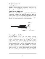
3.5mm Stereo Plug Wiring

5TE sensors used with Decagon loggers come with a 3.5mm
“stereo plug” connector. The stereo plug allows for rapid con-
nection directly to Decagon’s Em50 and Em50R dataloggers
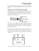
and to the hand-held ProCheck readers. Below is a diagram
showing the wiring configuration for this connector.

Extending Sensor Cables

Decagon supplies 10-foot (3m) and 50-foot (15.25m)
extension cables for use with the stereo plug type 5TE
sensors. You can safely connect up to four of the 50-foot
cables without signal attenuation. For field applications, it is

critical 

to seal the connections from the elements to maintain

a good connection and to prevent corrosion. It is imperative
that these connections are checked 

before

 the sensor is

buried. On the Decagon website you can access a step by step
photo tutorial of how to seal the connection. To access this
file go to www.decagon.com/literature/app_notes and click

Digital 
out

Ground 

Excitation

Summary of Contents for 5TE

Page 1: ...5TE Water Content EC and Temperature Sensors Operator s Manual Version 2...

Page 2: ...2008 Decagon Devices Inc All rights reserved Decagon Devices Inc 2365 NE Hopkins Court Pullman W A 99163 www decagon com...

Page 3: ...ater Content 6 Temperature 6 Electrical Conductivity 7 Converting Bulk EC to Pore EC 8 Pore Water vs Solution EC 9 4 Calibration 11 Dielectric Permittivity 11 Mineral Soil Calibration 11 Calibration i...

Page 4: ...vity 17 Temperature 18 6 Installing the Probes 19 Procedure 19 Orientation 21 Removing the Probes 21 Multiple Probe Installation 22 7 Campbell Scientific Programs 23 8 Troubleshooting Sensor Care 24 D...

Page 5: ...esolution a 0 1 a unitless from 1 20 0 75 a unitless from 20 80 VWC 0 0008 m3 m3 0 08 VWC from 0 to 50 VWC Accuracy a 1 a unitless from 1 40 soil range 15 from 40 80 VWC Using Topp equation 0 03 m3 m3...

Page 6: ...nt Output RS232 or SDI 12 contact Decagon for information on SDI 12 mode Operating Temperature 40 50 C Connector types 3 5 mm stereo plug or stripped and tinned lead wires Cable Length 5m standard cus...

Page 7: ...reby which is not manufactured by Seller shall be covered only by the warranty of its manufacturer Seller shall not be liable to Buyer for loss damage or injuries to per sons including death or to pro...

Page 8: ...e electrical array to measure electrical con ductivity Background Info In 2006 Decagon incorporated research from its EC 5 volu metric water content sensor into the ECH2O TE a sensor which measured vo...

Page 9: ...5TE Operator s Manual 2 About the 5TE 5 Figure 1 5TE Components...

Page 10: ...the probe Temperature The 5TE uses a surface mounted thermistor to take tempera ture readings It is located underneath the probe overmold next to one of the prongs and will read the temperature of the...

Page 11: ...cause significant inaccuracy in the EC measurement See the sensor cleaning section at the end of this manual for instructions on cleaning the probes if contamination occurs The 5TE uses a two electro...

Page 12: ...p between b and p Recent work by Hilhorst 2000 has taken advantage of the linear relationship between the soil bulk dielectric permittivity b and p to allow accurate conversion from b to p if the b is...

Page 13: ...a indicates that b 6 results in more accurate determinations of p Hilhorst 2000 offers a simple and easy method for determining for individual soil types which will improve the accuracy of the calcula...

Page 14: ...ectrical conductiv ity measurement on the water removed from the sample will give the solution electrical conductivity Theoretically the two are related by the bulk density An example calculation will...

Page 15: ...ielectric permittivity You are free to use any of these various transfer equations to convert raw dielectric permittivity data from the 5TE into VWC In Decagon s ProCheck reader and DataTrac and ECH2O...

Page 16: ...tivity of non soil media to VWC As with the former ECH2O TE sensor we plan to publish calibrations for com mon non soil media such as potting soil rockwool perlite etc but those investigations have no...

Page 17: ...r To download data to your computer you will need to install ECH2O Utility ECH2O DataTrac or a ter minal port program on your computer The following software support the 5TE sensor ECH2O Utility 1 10...

Page 18: ...for this connector Extending Sensor Cables Decagon supplies 10 foot 3m and 50 foot 15 25m extension cables for use with the stereo plug type 5TE sensors You can safely connect up to four of the 50 fo...

Page 19: ...on for this connector 5TE sensors with stripped and tinned cable option can be made with custom cable lengths up to 250ft on a per foot fee basis This option gets around the need for splicing wire a p...

Page 20: ...ter cable has a connector for the sensor jack on one end and three wires on the other end for connection to a datalogger this type of wire is often referred to as a pigtail adapter Both the stripped a...

Page 21: ...indicate the dielectric permittivity portion of the sensor is not working as expected The Raw value is converted to dielectric permittivity with the following equation Electrical Conductivity The raw...

Page 22: ...end the range of temperatures that can be represented by a 10 bit value The sensor sends temperature with 1 10 of a degree Celsius resolution for the range 40 to 50 0 C For the range 50 5 to 111 0 the...

Page 23: ...t install the 5TE next to large metal objects which can attenuate the probes electromagnetic field and distort output readings Because the probes have gaps between their prongs it is also important to...

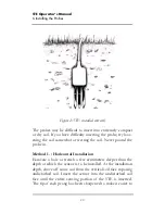
Page 24: ...g the soil Never pound the probe in Method 1 Horizontal Installation Excavate a hole or trench a few centimeters deeper than the depth at which the sensor is to be installed At the installation depth...

Page 25: ...a simple piece of PVC pipe with a notch cut in the end for the sensor to sit in with the sensor cable routed inside the pipe After inserting the sensor remove the installation device and backfill the...

Page 26: ...crew to pass through the nearby sen sor s ground screw thus producing an erroneous sensor read ing This problem occurs regardless of what logging system you are using if the ground wires are connected...

Page 27: ...connecting to a Campbell Scientific datalogger The following application notes containing Campbell Scientific sample programs are available for the 5TE Using the 5TE with Campbell Scientific CR10X Da...

Page 28: ...connections to the data logger are both correct and secure 2 Ensure that your data logger s batteries are not dead or weakened 3 Check the configuration of your data logger in ECH2O Utility or ECH2O D...

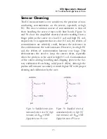
Page 29: ...all because the resistance in the soil dominates the total resistance However in a high EC soil the effects of contamination become very large This demonstrates the need to keep the screws clean espec...

Page 30: ...thoroughly with tap water to remove all remnants of soap 3 Dry the screws with a clean paper towel Use a scrubbing motion to dry the screws to be sure any particles have been detached Be sure that the...

Page 31: ...Dielectric soil moisture probe Model Number ECH2O TE ECH2O EC TM 5TE Year of First Manufacture 2005 This is to certify that the ECH2O TE ECH2O EC TM and 5TE dielectric soil moisture probes manufactur...

Page 32: ...eaning probe 26 screws 26 Contact Information 2 Converting bulk EC to pore EC 8 CSI loggers using 5TE probes with 23 D Declaration of Conformity 27 Dielectric Permittivity 11 17 E ECH2O Utility 1 10 1...

Page 33: ...21 removing the probe 21 L Logger Communication 16 M Mineral Soil Calibration 11 P Pore Water EC 8 Power Requirements 2 R Raw Values 17 S Screws 7 Seller s Liability 3 Sensor Accuracy 1 Sensor Cleani...

Page 34: ...5TE Operator s Manual Index 30 Specifications 1 T Temperature 6 18 Troubleshooting 24 V Vertical Installation 21 Volumetric Water content 6 W Warranty Information 3...

Reviews: