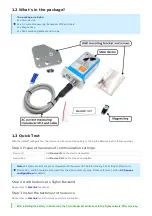
background image

Please refer to 

this link

 for details

Please refer to 

this link

 for instructions on battery installation.

Please refer to section 

1.4 Uplink Payload and Data Decoding

 for details of decoding the receiving packet to get

the measured values.

For the Uplink Payload structure, please refer t

this link

.

Figure 3. Dimensions of Sigfox Transmitter

Figure 4. Dimensions of V1A vibration sensor module

The Sigfox-Ready V1A vibration sensor combines a wireless transmitter WSSFC and a V1A vibration sensor. Therefore,
the installation will be divided into 02 parts:

INSTALLATION GUIDE FOR V1A SENSOR MODULE

INSTALLATION GUIDE FOR WIRELESS

TRANSMITTER.

PLEASE SEE THE BELOW STEPS.

Mount the wireless transmitter on the wall or a pole nearby the object to monitor the vibration. The wireless
transmitter must be mounted at the minimum level of 2m from the ground for a better RF signal. To get the

Step 2: Add the device to Sigfox Backend

Step 3: Install the batteries to the device

After installing the battery in 60 seconds, the first data packet will be sent to the Sigfox network. After receiving
the first data packet, the time of another packet depends on the value of the parameter:
CYCLIC_DATA_PERIOD. Additionally, you can use a Magnet Key to force the device to send data instantly.

Step 4: Decode the payload of receiving package

1.4 Uplink Payload and Data Decoding 

Note: Please select the right Payload document to suit the FW version of the sensor

1.5 Sensor Installation

1.5.1 Dimension drawings

1.5.2 Installation

Summary of Contents for Sigfox WSSFC-AC FW1

Page 1: ...AC Current Sensor WSSFC AC FW1 Manual for Sigfox Ready Air Gas Flow Sensor WSSFC M12F AFD FW1 Manual for Sigfox Ready Single Axis Vibration Sensor WSSFC V1A FW2 Manual for Sigfox Ready AC Current Sen...

Page 2: ...sion Item Changes Changed by Changed Date Approved by Approved Date 1 Initial version D Q Tuan 09 04 2022 N V Loc 28 06 2022 To use this product please refer step by step to the below instructions Ope...

Page 3: ...for more details The uplink payload will tell the user the HW version FW version and current configuration of the device Case 5 During commissioning testing or calibration sensor the user can force t...

Page 4: ...rent measuring transducer M12 and cable 01 x Magnet key 01 x Wall mounting bracket and screws 1 3 Quick Test Step 1 Prepare the values of communication settings Note All Sigfox sensors are pre configu...

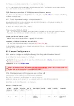
Page 5: ...t to suit the FW version of the sensor 1 5 Sensor Installation SAFETY ATTENTION TO REPLACE BATTERIES OR SERVICE THE MAIN DEVICE PLEASE PAY ATTENTION TO THE ELECTRICAL SHOCK THAT MAY HAPPEN DUE TO THE...

Page 6: ...t the best RF signal As the AC current transducer will be attached to the wireless transmitter please make sure the cable length is enough for the distance from CT to the wireless transmitter Mount th...

Page 7: ...e value zero no AC current Then you can turn ON the main load again to put the system into the operation You can use a clamp type ampere meter to validate the value reading from the system Please make...

Page 8: ...values during calibration The scaled current will be multiplied by the CT ratio to deliver the final value which is the actual load current that the user wants to measure Scaled_CT_Current A x CT_Cur...

Page 9: ...thod 1 Configuring via Downlink message Please find the instructions inthis link but please take note of the FW version of the Document Method 2 Configuring via offline cable Some parameters are read...

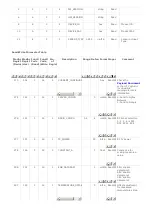
Page 10: ...276 114 3 16 1 RADIO_CONFIG 1 4 4 uint16 Read Write RC zones selection 1 2 3 4 is RC1 RC2 RC3s RC4 277 115 3 16 1 TX_POWER 20 int16 Read Write RF Tx power 278 116 3 16 2 CONSTANT_A 1 float Read Write...

Page 11: ...link Please refer to the detailed specifications inthis link For warranty terms and support procedures please refer tothis link Use cases Case studies White papers END 3 3 Calibration for Sigfox Read...

Page 12: ...Connectivity Type Sigfox Product Type 2 parts Mounting Type Direct process mounting for the whole set Powered by 2 x AA batteries 1 5V Information Changes in this version v s previous version Item Ch...

Page 13: ...ails The uplink payload will tell the user the HW version FW version and current configuration of the device Case 5 During commissioning testing or calibration sensor the user can force the device to...

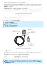
Page 14: ...C The instruction for installing the batteries is in this link Figure 1 Battery Energizer L91 For Battery life estimation please refer to this link Figure 2 Product package of WSSFC M12F AFD Figure 3...

Page 15: ...pre configured with the correct RC before delivery The settings of Device ID Device PAC and RC could also be read from the device memory map Please reference section 3 2 Sensor configuration for detai...

Page 16: ...Figure 4 Dimensions of WSSFC M12F AFD...

Page 17: ...tem to see whether the wireless transmitter already sent the first message to the system Please follow this link to learn how to install the batteries Attach the wireless transmitter to the AFD probe...

Page 18: ...2F AFD and AFD 0200 The AFD Air Gas Flow Sensor measures pressure and temperature in the duct or pipe The Sigfox Ready wireless transmitter is to read the parameters of the probe like differential pre...

Page 19: ...figuring via Downlink message Please find the instructions inthis link but please take note of the FW version of the Document Method 2 Configuring via offline cable Some parameters are read only and s...

Page 20: ...e 276 114 3 16 1 RADIO_CONFIG 1 4 4 uint16 Read Write RC zones selection 1 2 3 4 is RC1 RC2 RC3s RC4 277 115 3 16 1 TX_POWER 20 int16 Read Write RF Tx power 278 116 3 16 2 CONSTANT_A 1 float Read Writ...

Page 21: ...t Read Write Fluid Density default is Air Please refer to this link Please refer to the detailed specifications inthis link For warranty terms and support procedures please refer tothis link Use cases...

Page 22: ...Type Sigfox Product Type 2 parts Mounting Type Direct process mounting for sensor wall mount for transmitter Powered by 2 x AA batteries 1 5V Information Changes in this version v s previous version...

Page 23: ...sor if the measured value passed the threshold it will send the uplink message immediately This message is called ALARM The payload also tells the user the data like measured values battery level alar...

Page 24: ...efer to this link Figure 2 Product package of WSSFC V1A 025 With the default configuration the device can be connected quickly to the Sigfox Network by the following steps Device ID Get Devive ID on t...

Page 25: ...BELOW STEPS Mount the wireless transmitter on the wall or a pole nearby the object to monitor the vibration The wireless transmitter must be mounted at the minimum level of 2m from the ground for a b...

Page 26: ...he V1A sensor module as below figure Figure 5 Complete set of WSSFC V1A 025 vibration sensor Please refer to this link Problems with Sigfox communication like not receiving the packets please refer to...

Page 27: ...link The Daviteq Sigfox Ready V1A Single axis Vibration Sensor comprises 02 parts connected together as shown below picture The Daviteq Sigfox Ready wireless transmitter The Daviteq V1A vibration sen...

Page 28: ...downlink or offline tools For more other configuration parameters please refer to the next section Sensor configuration can be configured in 02 methods Method 1 Configuring via Downlink message Pleas...

Page 29: ...d to Dongle 276 114 3 16 1 RADIO_CONFIG 1 4 4 uint16 Read Write RC zones selection 1 2 3 4 is RC1 RC2 RC3s RC4 277 115 3 16 1 TX_POWER 20 int16 Read Write RF Tx power 278 116 3 16 2 CONSTANT_A 1 float...

Page 30: ...For warranty terms and support procedures please refer tothis link Use cases Case studies White papers END 6 References...

Page 31: ...ion Item Changes Changed by Changed Date Approved by Approved Date 1 Initial version D Q Tuan 24 06 2023 N V Loc 28 06 2023 To use this product please refer step by step to the below instructions Oper...

Page 32: ...for more details The uplink payload will tell the user the HW version FW version and current configuration of the device Case 5 During commissioning testing or calibration sensor the user can force t...

Page 33: ...rent measuring transducer M12 and cable 01 x Magnet key 01 x Wall mounting bracket and screws 1 3 Quick Test Step 1 Prepare the values of communication settings Note All Sigfox sensors are pre configu...

Page 34: ...t to suit the FW version of the sensor 1 5 Sensor Installation SAFETY ATTENTION TO REPLACE BATTERIES OR SERVICE THE MAIN DEVICE PLEASE PAY ATTENTION TO THE ELECTRICAL SHOCK THAT MAY HAPPEN DUE TO THE...

Page 35: ...t the best RF signal As the AC current transducer will be attached to the wireless transmitter please make sure the cable length is enough for the distance from CT to the wireless transmitter Mount th...

Page 36: ...e value zero no AC current Then you can turn ON the main load again to put the system into the operation You can use a clamp type ampere meter to validate the value reading from the system Please make...

Page 37: ...values during calibration The scaled current will be multiplied by the CT ratio to deliver the final value which is the actual load current that the user wants to measure Scaled_CT_Current A x CT_Cur...

Page 38: ...ng via Downlink message Please find the instructions inthis link but please take note of the FW version of the Document Method 2 Configuring via offline cable Some parameters are read only and some ar...

Page 39: ...nd to Dongle 276 114 3 16 1 RADIO_CONFIG 1 4 4 uint16 Read Write RC zones selection 1 2 3 4 is RC1 RC2 RC3s RC4 277 115 3 16 1 TX_POWER 20 int16 Read Write RF Tx power 278 116 3 16 2 CONSTANT_A 1 floa...

Page 40: ...link Please refer to the detailed specifications inthis link For warranty terms and support procedures please refer tothis link Use cases Case studies White papers END 3 3 Calibration for Sigfox Read...

Page 41: ...ty Type Sigfox Product Type 2 parts Mounting Type Direct process mounting for sensor wall mount for transmitter Powered by 2 x AA batteries 1 5V Information Changes in this version v s previous versio...

Page 42: ...sor if the measured value passed the threshold it will send the uplink message immediately This message is called ALARM The payload also tells the user the data like measured values battery level alar...

Page 43: ...efer to this link Figure 2 Product package of WSSFC V1A 025 With the default configuration the device can be connected quickly to the Sigfox Network by the following steps Device ID Get Devive ID on t...

Page 44: ...BELOW STEPS Mount the wireless transmitter on the wall or a pole nearby the object to monitor the vibration The wireless transmitter must be mounted at the minimum level of 2m from the ground for a b...

Page 45: ...he V1A sensor module as below figure Figure 5 Complete set of WSSFC V1A 025 vibration sensor Please refer to this link Problems with Sigfox communication like not receiving the packets please refer to...

Page 46: ...link The Daviteq Sigfox Ready V1A Single axis Vibration Sensor comprises 02 parts connected together as shown below picture The Daviteq Sigfox Ready wireless transmitter The Daviteq V1A vibration sen...

Page 47: ...onfiguration parameters can be changed by downlink or offline tools For more other configuration parameters please refer to the next section Sensor configuration can be configured in 02 methods Method...

Page 48: ...k the Payload Document section 5 Payload for downlink message for more information 274 112 3 16 1 SERVER_CONFIG 0 uint16 Read Write 0 Send to Sigfox Network 1 Send to Dongle 276 114 3 16 1 RADIO_CONFI...

Page 49: ...of measurement cycle for communication timeout between sensor module and lorawan module Please refer to this link Please refer to the detailed specifications inthis link For warranty terms and support...

Reviews: