background image

9

Function
Description

Selector

Switch

Position

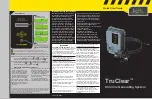
Functions and Instructions

Set Clock

1

Set the current time on the digital clock.

Select the 

Set Clock

 position on the selector switch to enable the time of day to 

be input. A number ‘

1

’ will appear at the left of the screen.

(a) The display will flash on and off as long as the selector switch remains at this 

position. Use the up 

▲ 

and down 

▼ 

buttons to reach 

the desired times. Hold the buttons down for fast increments.

Set Timer 1 – ON

2

Set the start time for the first run time sequence.

Select the 

Set Timer 1 – ON

 position on the selector switch. A number ‘

2

’ will 

appear at the left of the screen.

This time is factory pre-set to 6am. Proceed as per (a) in the ‘Set Clock’ 

instruction to change time.

To disable this timer, move up or down to 11.59PM. Press the UP button one 

more time to turn OFF. 

NOTE:

 This step will also disable the time for ‘Set Timer 

1 – OFF’.

Set Timer 1 – OFF

3

Set the completion time of the first run time sequence.

Select the 

Set Timer 1 – OFF

 position on the selector switch. A number ‘

3

’ will 

appear at the left of the screen.

This time is factory pre-set to 8am. Proceed as per (a) in the ‘Set Clock’ 

instruction to change time. 

Set Timer 2 – ON

4

Set the start time for the second run time sequence.

Select the 

Set Timer 2 – ON

 position on the selector switch. A number ‘

4

’ will 

appear at the left of the screen.

This time is factory pre-set to 5pm. Proceed as per (a) in the ‘Set Clock’ 

instruction to change time.

To disable this timer please refer to selector switch position 2 above.

Set Timer 2 – OFF

5

Set the completion time for the second run time sequence.

Select the 

Set Timer 2 – OFF

 position on the selector switch. A number ‘

5

’ will 

appear at the left of the screen.

This time is factory pre-set to 11pm. Proceed as per (a) in the ‘Set Clock’ 

instruction to change time.

To disable this timer please refer to selector switch position 4 above.

Automatic ON

6

Filtration system switches on and off automatically according to your set times.

Select the 

Automatic ON

 position on the selector switch. A number ‘

6

’ will 

appear at the left of the screen.

Manual ON

7

Overrides the automatic time clock settings and switches filtration system ON.

Select the 

Manual ON

 position on the selector switch. A number ‘

7

’ will appear 

at the left of the screen.

NOTE: Chlorination will be constant until turned OFF or back to Automatic ON. 

Over chlorination may occur if left for long durations. 

OFF

8

Overrides the automatic time clock settings and switches filtration system OFF.

Select the 

OFF

 position on the selector switch. A number ‘

8

’ will appear at the 

left of the screen.

NOTE: Chlorination / sanitisation will cease. Not recommended for long 

durations. 

Summary of Contents for ChloroMatic MC16C

Page 1: ...com au Salt Water Pool System Models MCS16C MCS16CTP MC16C MCS24C MCS24CTP MC20C MCS36C MCS36CP MC30C MCS40C MCS50C Installation Operating Instructions ChloroMatic Please pass these instructions on to...

Page 2: ...with earth bolt 50mm 5 Mounting Kit and Spare Fuse 6 2 x 80 50mm reducing sockets 7 2 x 80mm Nut 8 2 x 80mm Socket Packing List 2 Important Notice 3 Installation Instructions 3 Pre Start Up Procedure...

Page 3: ...l is recommended The Cell is the clear plastic housing containing the removable cell head During the chlorination process a white powdery Calcium scale may naturally build up on the titanium plates in...

Page 4: ...ave been provided for fast and simple installation Simply cut out Template at bottom of page 19 for location of drill entry points Use a 7mm masonry drill bit when fitting Power Supply to a brick or c...

Page 5: ...f pool and allow vacuum to continue for a further 2 or 3 hours Salt should now be completely mixed Never add salt directly into skimmer box CHLORINE For a new pool installation that has not been chlor...

Page 6: ...d off Refer Sanitiser Output page 7 FLOW STAND BY ON Green Green 1 Gas detected Check pump pipes for damage 2 Gas sensor not connected to cell FLUCTUATING AROUND 100 Green Green System operating norma...

Page 7: ...ck its operation simply turn the Sanitiser Output Control to MAX and the Cell will turn ON Once checked adjust the Sanitiser Output Control back to the desired position and after a few minutes the Cel...

Page 8: ...designed to operate at swimming season water temperatures When the pool begins to cool in the off season the temperature drop causes the Cell to behave differently it will draw less electrical curren...

Page 9: ...ime sequence Select the Set Timer 2 ON position on the selector switch A number 4 will appear at the left of the screen This time is factory pre set to 5pm Proceed as per a in the Set Clock instructio...

Page 10: ...the Terminal Block provided Fasten screws Multi voltage connections Refer to table and diagram below for wiring instructions Please Note Only one light can be connected to each light transformer If mo...

Page 11: ...s with hard water reverse polarity systems may require occasional manual cleaning Life of ChloroMatic electrolytic cells vary substantially from one installation to another due to variations in operat...

Page 12: ...spot staining cloudy water etc An incorrect pH level can damage the pool Correct pH levels are as follows Fibreglass 7 2 to 7 4 Concrete tiled 7 4 to 7 6 If you allow the pH level to rise to 8 0 or a...

Page 13: ...N SWIMMING IN THE POOL In extremely hot weather or during periods of heavy bathing loads the running time may need to be extended to 10 14 hours per day In some cases you may find your chlorine level...

Page 14: ...Cell ppm An abbreviation for Parts Per Million the accepted measurement of chemical concentration in swimming pool water I ppm l mg L The appropriate chlorinator size for your pool is dependent on the...

Page 15: ...easured pH SET This will allow adjustment of the controller set point using adjustment tool Turn clockwise to increase the set point Note that acid pump is off when adjusting set point OFF Disables th...

Page 16: ...tance horizontally between Pump Module and Chemical Drum is 1 0 metres 8 Using PVC cement fit Probe Injector Housing to suction or return line before the cell and ensure probe is horizontal to the gro...

Page 17: ...warnings on the acid container Dip the end of the sensor in the solution and move it around for about 20 seconds Rinse the sensor and return it to the manifold The pH Control should be turned off for...

Page 18: ...18 Notes Service History...

Page 19: ...19...

Page 20: ...date of original purchase when claiming under the Davey Guarantee Davey shall not be liable for any loss of profits or any consequential indirect or special loss damage or injury of any kind whatsoev...

Reviews: