2: Installation
RT7000-MSOP
2-3
Rear Panel Connections
The rear panel of the RT7000 is made of die cast aluminum and is attached to
the rear side panels by 4 hex head bolts. The heat sink maintains the
temperature within operational specifications eliminating the need for an
internal cooling fan. It fills most of the rear panel area leaving room for the
fan power connector and optional pre/postselector RF connections.
The accessory, remote control and RF connections are wired to the Interface/
Power supply board.
Power to the
RT7000
Input power for the RT7000-12 is nominally 13.8 Vdc, with a maximum
current requirement of 25A. The recommended operational voltage range of
the transceiver is 11 to 15.5 Vdc. The RT7000-28 re28 Vdc at a
maximum of 15A (range of 22-30 Vdc). The DC input connector on the rear
panel is a 2 pin, 30A circular receptacle that has a square mounting flange
with 2 male pins. The mating plug is attached to the input DC power cable
(C991556). This cable, supplied with the RT7000, has a convenient
connection to a variety of DC power sources. For specific connections,
refer
to the "Power Cabling Accessories" figure on page 2-6.
The DC power connection between the RT7000 and its power source should
be as short as possible. If a Datron power cable is not available, use a 14 AWG
cable for runs up to 3 feet, a 12 AWG cable for runs to 9 feet, or a 10 AWG
cable for longer runs.
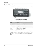
Figure 2-2. Rear Panel Connections
DC
Input
Accessory
1
Accessory
2
Accessory
3
Remote
Control
Fuse
Antenna
Fan

