Compact Airway modules
Document No. 800 1009-1
21
2.3
Connectors and signals
13
1
14
25
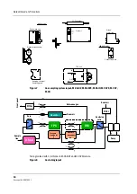
Figure 15
Module bus connector pin layout
Table 2
Module bus connector pin description
Pin No I/O Signal
1
I
RESET RS485
2
I
-15 VDC
3
I
+15 VDIRTY
4
I
+15VDC
5
I/O
-DATA RS485
6
I/O
DATA RS485
7
Ground and Shield
8
I
-RESET RS485
9
n/c
10
n/c
11
n/c
12
n/c
13
Ground and Shield
14
I
+24/+32 VDIRTY depends on power supply (not used)
15
I
Ground DIRTY
16
n/c
17
n/c
18
n/c
19
n/c
20
I
GASFR (not used)
21
I
CTSD (not used)
22
I
TXDD (not used)
23
O
RXDD (not used)
24
I
+5 VDC
25
I
+5 VDC DIRTY, for infrared lamps


