


Compact Airway modules
Document No. 800 1009-1
15
Pneumatic unit
The pneumatic unit contains zeroing valve, occlusion valve and tubing connections. There is a
series of restrictors and chambers forming a pneumatic filter to prevent pressure oscillations from
the pump to reach the measuring units. The occlusion valve connection to room air includes a dust
filter and the zero valve connection to room air includes an absorber.
Connection block
The connection block contains sample gas outlet connector and OM unit reference gas inlet. The
inlet is equipped with a dust filter.
Occlusion valve
The valve is activated when the sampling line gets occluded. The main flow is then diverted to the
side flow of the D-fend water trap to faster remove the occlusion.
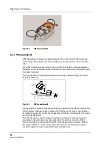
Sampling pump and damping chamber
The gas sampling pump is a membrane pump that is run by a brushless DC-motor. Sample flow is
measured with a differential pressure transducer across a known restriction. The motor is
automatically controlled to maintain a constant flow, even when the D-fend water trap ages and
starts to get occluded. It also enables use of sample tubes with varying lengths and diameters.
The damping chamber is used to even out the pulsating flow and silence the exhaust flow.
NOTE: In no occasion is the flow reversed towards patient.
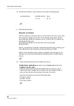
OUT
IN
B1
B2
E
D
C
B
A
F
Pneumatic unit
Damping champer
Sampling pump
TPX unit
D-fend
Water trap
Connection block
Pressure transducers
OUT
IN
Nafion tube
G
CO2 absorber
Nafion tube
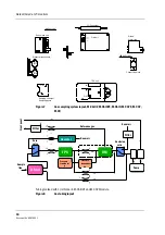
Figure 6
Gas sampling system layout, M-C


