background image


DT1012 IP 

32


20221107-V0 


9. Dismounting


9.1. Dismounting procedure


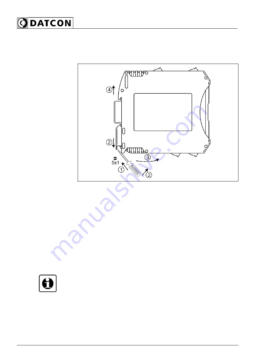
The following figure shows the dismounting procedures: 

Dismounting from the 
rail


The dismounting procedure needs a screwdriver for slotted screws. 
 
1. Switch off the power supply 
2. Disconnect all wires. 
3. Put the screwdriver end into the fixing assembly’s hole (figure 

step 1.). 

4. Lift the screwdriver handle until it possible to open the fixing 

assembly (figure step 2.). 

5. Keeping the screwdriver in this position lift the instrument bottom 

from the bottom edge of the rail (figure step 3.). 

6. Lift the whole instrument (you may put out the screwdriver) (figure 

step 4), the instrument will be free. 


9.2. Disposal


According with the concerning EU directive, the manufacturer 
undertakes the disposal of the instrument that are manufactured by it 
and intended to be destroyed. Please deliver it in contamination-free 
condition to the site of the Manufacturer or to a specialized recycling 
company. 

stop 


Summary of Contents for DT1012 IP

Page 1: ...DT1012 IP PS Temperature Resistance Potentiometer Transmitter Operating Instructions...

Page 2: ...3 4 Setting 8 3 5 Indicator LEDs USB connector 9 3 6 Storage and transport 9 4 Mounting 10 4 1 General instructions 10 4 2 A k sz l k f bb m retei 10 4 3 Mounting 11 5 Connecting 12 5 1 Preparing the...

Page 3: ...25 7 2 4 Resistor setting 26 7 3 Analogue output setting 27 7 4 Factory default resetting 28 7 6 Display measuring values 29 7 7 Display instrument information 29 7 8 Display USB communication inform...

Page 4: ...f this manual should be made available to these personnel and put into practice by them 1 3 Symbolism used Information tip note This symbol indicates helpful additional information Caution warning dan...

Page 5: ...system components through incorrect mounting or adjustment 2 4 General safety instructions The DT1012 IP is a high tech instrument requiring the strict observance of standard regulations and guideline...

Page 6: ...t description 3 1 Delivery configuration Delivered items The scope of delivery encompasses DT1012 IP PS documentation this operating instructions Certificate mini USB 5 pin USB A cable Configuration s...

Page 7: ...vel signal averaging etc are done via USB port The configuration program running on the PC and the USB cable are included with the instrument The transmission characteristics of the transmitter are ex...

Page 8: ...isolation the output stage converts it into an analog current signal passive output external power supply required The instrument generates the power supply voltages required for the input side and t...

Page 9: ...ent with a continuous green light 3 6 Storage and transport This instrument should be stored and transport in places whose climatic conditions are in accordance with chapter 10 1 Technical specificati...

Page 10: ...hnical specification as described under the title Ambient conditions Mounting position The instruments are designed in a housing for mounting on TS 35 rail The instruments should be mounted in vertica...

Page 11: ...ired for installation 1 In the position shown in the figure place the fixing groove of the instrument on the upper edge of the rail step 1 in figure 2 Push the lower part of the instrument towards the...

Page 12: ...e of supply voltage Use only a screwdriver with appropriate head Take note the suitability of the connecting cable wire cross section insulation etc The wire cross section should be 0 25 1 5 mm2 You m...

Page 13: ...2 Connecting sensor resistor potentiometer to the input The following figure shows the wiring plan connecting the sensor resistor potentiometer to the input Wiring plan connecting the sensor resistor...

Page 14: ...cording to the wiring plan 3 Screw the terminal in 4 Check the hold of the wires in terminals by pulling on them firmly Checking the Connections Check if the cables are connected properly have you con...

Page 15: ...sing unit Be careful the polarity of the cables Leave connection terminals 3 and 4 free 1 Loosen terminal screws 2 Insert the wire ends into the open terminals according to the wiring plan 3 Screw the...

Page 16: ...ply Polarity is indifferent 1 Loosen terminal screws 2 Insert the wire ends into the open terminals according to the wiring plan 3 Screw the terminal in 4 Check the hold of the wires in terminals by p...

Page 17: ...into the open terminals according to the wiring plan 3 Screw the terminal in 4 Check the hold of the wires in terminals by pulling on them firmly Checking the connections Check if the cables are conn...

Page 18: ...he PC side 3 Make the desired settings as described in chapter 7 Setting up USB driver installation is not required It is not necessary to supply the instrument with power while making the settings Af...

Page 19: ...ection points to be connected PI 7 PI 8 Pt 9 and Pt 10 Output type 4 20 mA passive Error indication On Analog output scaling lower value 4 mA 200 C Analog output scaling upper value 20 mA 800 C Output...

Page 20: ...ed flashing light The sequence number of the error is given by the number of flashes 3 on indicator which indicates the power on state of the instrument with a continuous green light Error status indi...

Page 21: ...tory as the PIC32MM exe setup program Setup steps 1 Connect the instrument to the PC with the included USB cable If you want to check the input signal then put the instrument under power If you just w...

Page 22: ...e connected to the input of the instrument Pt temperature sensor Potentiometer Scaled potentiometer Resistor Factory default Pt temperature sensor Setup steps 1 Click the Pt Potentiometer R button in...

Page 23: ...number you want to use 4 Select the measurement time you want to use 5 If you want to correct the error of the Pt sensor you can do it at 3 points 6 Store the settings by clicking the Write to instru...

Page 24: ...4 Select the measurement time you want to use 5 Set the potentiometer to initial value 6 Click the 0 button 7 Set the potentiometer to final value 8 Click the 100 button 9 Store the settings by clicki...

Page 25: ...tentiometer to initial value 6 Click the 0 button 7 Set the potentiometer to final value 8 Click the 100 button 9 Store the settings by clicking the Write to instrument button 10 Set the decimal point...

Page 26: ...4 Resistor setting 3 Select the wire number you want to use 4 Select the measurement time you want to use 5 Store the settings by clicking the Write to instrument button 6 Close the settings window by...

Page 27: ...above 20 mA Lower scale value Upper scale value Factory defaults see figure below Setup steps 1 Click the Analogue button in the OUTPUT field 2 In the window that appears make the necessary settings 3...

Page 28: ...e values in the instrument exit by pressing the Exit Esc button or read the current settings from the instrument It can be advantageous if the desired setting differs only slightly from the factory se...

Page 29: ...s there is a communication connection between the PC and the instrument in the middle of the configuration program window 7 7 Display instrument information Function The configuration program displays...

Page 30: ...strument only receives power from the USB port Error 1 is still displayed because in this case the input module of the instrument does not receive power so the instrument perceives it as faulty Error...

Page 31: ...count the flashes of the red indicator and find the error interpretation in chapter 7 9 Error display If you cannot eliminate the error based on the error detection result incorrect input signal inco...

Page 32: ...it possible to open the fixing assembly figure step 2 5 Keeping the screwdriver in this position lift the instrument bottom from the bottom edge of the rail figure step 3 6 Lift the whole instrument...

Page 33: ...rrent Output signal DC current Output ranges 4 20 mA Overload 22 5 mA Loop power 8 30 VDC Transfer characteristics Output signal error 25 C 2 C 0 1 Non linearity hysteresis 0 02 max Temperature coeffi...

Page 34: ...horizontal rail position A version with an operating temperature range of 20 to 60 C is also available Electromagnetic compatibility EMC Accordance with the standard MSZ EN IEC 61326 1 and MSZ EN 550...

Page 35: ...DT1012 IP 20221107 V0 35...

Page 36: ......

Reviews: