


47
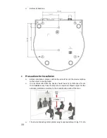
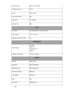
10. Component Video Output –
DSub PIN Assignments
PIN
No.
PIN
Name
Signals
1
RED
Red Video
2
GREEN
Green Video
3
BLUE
Blue Video
4
ID2/RES
Reserved
5
GND
Ground (HSync)
6
RED_RTN
Red return
7
GREEN_RTN Green return
8
BLUE_RTN
Blue return
9
KEY/PWR
+5V DC
10
GND
Ground (VSync)
11
ID0/RES
Reserved
12
ID1/SDA
I
2
C Data
13
HSync
Horizontal sync
14
VSync
Vertical sync
15
ID3/SCL
I
2
C Clock
Summary of Contents for PTC-120
Page 1: ...1 ...
Page 14: ...14 16 Service Switch Page 43 Service switch is used to set the respective firmware upgrades ...
Page 32: ...32 Metal plate A Machine Side Metal plate A Locking Screw Metal plate A Machine Side ...
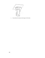
Page 35: ...35 Finally remove the screws on the hanger and the device ...
Page 53: ...53 ...
Page 62: ...62 Notes ...
Page 63: ...63 Notes ...
Page 64: ...64 15 Service Support ...


