34
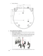
be installed on the ceiling, please use the UL security certified hanger to
prevent the device from falling.
Please check whether the camera is installed securely on a regular basis
.
•
Installation Steps
Please configure the resolution by adjusting the DIP switch first (
Please
refer to the
DIP Switch
section (Page 40) for the
relevant descriptions of
DIP switch).
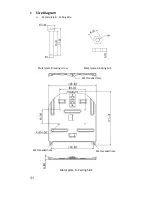
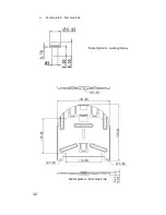
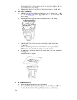
Secure metal Plate A to the base of the camera using 4 M3 screws
Fix the metal Plate B to a secure ceiling position using 4 M3 screws
※
Caution:
Please use the hanger that has obtained the UL security certification.
Please reserve the hole for connecting wires of the camera.
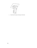
Mechanically slide metal plate A into metal plate B so they marry and
latch together
Secure using 3 M3 screws
•
How to Remove
Remove the connecting wires from the camera
To uninstall the camera from the ceiling, loosen the three screws that fix
metal plates A and B and then push the device to the left to remove
Summary of Contents for PTC-120
Page 1: ...1 ...
Page 14: ...14 16 Service Switch Page 43 Service switch is used to set the respective firmware upgrades ...
Page 32: ...32 Metal plate A Machine Side Metal plate A Locking Screw Metal plate A Machine Side ...
Page 35: ...35 Finally remove the screws on the hanger and the device ...
Page 53: ...53 ...
Page 62: ...62 Notes ...
Page 63: ...63 Notes ...
Page 64: ...64 15 Service Support ...


