


Removal and Replacement
4-5
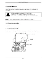
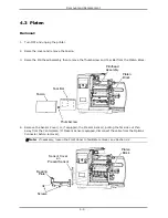
4.3 Platen
Removal:
1.
Turn OFF and unplug the printer.
2.
Raise the cover and remove the Fascia.
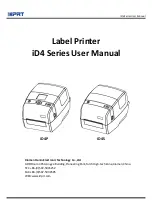
3.
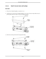
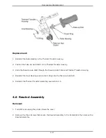
Raise the Printhead Assembly then remove the Thumbscrew and Tear Bar from the Platen Block.
Thumbscrew
Tear Bar
Platen
Block
Fascia
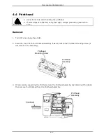
Printhead
Assembly
4.
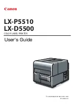
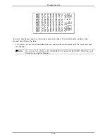
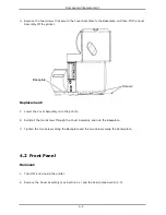
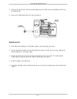
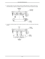
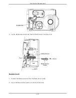
Remove the Sensor Cover (or, if equipped, the Present Sensor), pulling the far side out then
away from the Centerplate. (If Present Sensor equipped, disconnect the cable from the Options
Connector before removal).
Note: If necessary, loosen the Front Panel to facilitate removal; see Section 4.2.
Screws
Sensor Cover
-or-
Present Sensor
Bearing
Plate
Platen
Block
Summary of Contents for I-Class
Page 1: ...I Maintenance Manual...
Page 4: ...ii...
Page 5: ...i 1 Overview 1 0 Introduction 1 1 1 About the Printer 2...
Page 6: ...ii...
Page 38: ...ii...
Page 56: ...ii 4 11 Main Logic PCB 27 4 12 Backplane PCB 29...