


8
QuickScan™ I QM21X1 / QBT21X1
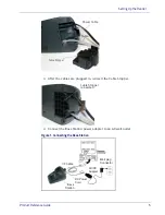
System and Network Layout
Typical Setup with Cradle and Host
Figure 5. Reader Layout
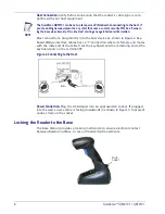
Connecting the Base when Security Pin is Enabled
When connecting the Base to a system that has a custom Security Pin enabled,
follow the steps below in the order shown:
1. Power down the host system.
2. Connect the appropriate interface cable into the Base
as shown
.
3. Place the reader in the Base.
4. Power up the host. The reader will link to the Base
5. When the host completely powers up, a new custom Security Pin Code may
be sent to the reader and Base, depending on host configuration. Contact
Datalogic Technical Support for more information.
Reader
Base Station
Host
Power Supply
NOTE
If you want to change security settings or set up a PIN, see
"BT Security Mode"
starting
on page 223.
Summary of Contents for QuickScan I QM2131
Page 62: ...Enter Exit Programming Mode USB Keyboard Speed 52 QuickScan I QM21X1 QBT21X1 NOTES...
Page 98: ...Enter Exit Programming Mode Green Spot Duration 88 QuickScan I QM21X1 QBT21X1 NOTES...
Page 264: ...Symbologies 254 QuickScan I QM21X1 QBT21X1 NOTES...
Page 284: ...Enter Exit Programming Mode 274 QuickScan I QM21X1 QBT21X1 NOTES...
Page 324: ...314 QuickScan I QM21X1 QBT21X1 NOTES...
Page 340: ...330 QuickScan I QM21X1 QBT21X1 NOTES...
Page 344: ...334 QuickScan I QM21X1 QBT21X1 NOTES...
Page 346: ...336 QuickScan I QM21X1 QBT21X1 5 6 7 8 9...
Page 347: ...Product Reference Guide 337 A B C D E F...


