background image

E-GENIUS

212

   AV7000 LINEAR CAMERA

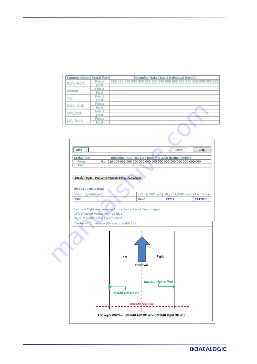
Diagnostics | Serial Comm Status

Use the

 Serial Comm Status

 window to view the serial data being received by the camera 

from the focusing device.

To access the Serial Comm Status window:

In the menu tree under

 Diagnostics

, click 

Serial Comm Status

. The 

Serial Comm Status 

window opens. Displays serial messages received. 

Serial Comm Status Example 1

Serial Comm Status Example 2

Summary of Contents for AV7000

Page 1: ...AV7000 PRODUCT REFERENCE GUIDE Linear CAMERA...

Page 2: ...ions please let us know via the Contact page Disclaimer Datalogic has taken reasonable measures to provide information in this manual that is complete and accu rate however Datalogic shall not be liab...

Page 3: ...on Description 1 General View 1 Field Procedure Quick Cross Reference 2 Reading Station Overview 2 Image Acquisition 3 Pulsed Illumination 4 Applications 5 Model Description 6 AV7000 and AI7000 Versio...

Page 4: ...onnection Block Diagrams 48 Single Head AV7000 with DM3610 49 Easy DM3610 and AV7000 49 Single Head AV7000 with RangeFinder 50 Single Head AV7000 with LCC 75xx Light Curtain Kit 50 Multi Head AV7000 w...

Page 5: ...103 AV7000 Timing and Distance Diagrams 111 Bottom Upstream AV7000 Configuration 112 Fixed Focus NONE 113 Focusing with a Light Curtain 114 Focusing with a Light Curtain and S80 115 Focusing with an...

Page 6: ...iagnostics Multiple Camera Viewer Multi Viewer 216 Diagnostics Multiple Symbol Viewer 217 Diagnostics Log Viewer Decoder 218 Diagnostics Log Viewer Real Time Process 219 Diagnostics Scope Calibration...

Page 7: ...R 7 AV7000 FEATURES 286 LED Indicators 286 AV7000 LEDs 286 AI7000 Illumination LEDs 288 Control Panel Buttons 288 Setting up WebSentinel PLUS in the AV7000 289 Using WebSentinel to View AV7000 Images...

Page 8: ...E GENIUS viii AV7000 LINEAR CAMERA Replacing an AV7000 Camera 324 Replacing AV7000 with a Failed Memory Card 326 Connecting a defaulted AV7000 back into a Cluster 329 CHAPTER 10 TECHNICAL FEATURES 332...

Page 9: ...res that may be useful in improving maintaining or enhancing the performance of the hardware or software being dis cussed This symbol identifies a hazard or procedure that if incorrectly performed cou...

Page 10: ...Hover over the Support Service menu for access to Services and Technical Support REFERENCE DOCUMENTATION The documentation related to the AV7000 camera system management is listed below S60 Series In...

Page 11: ...tions RISK GROUP EXEMPT LED emission according to EN 62471 Avoid staring at the LEDs as one would with any very strong light source such as the sun A safety device is included that switches the LED il...

Page 12: ...eference contacts Since April 20th 2016 the main European directives applicable to Datalogic products require inclusion of an adequate analysis and assess ment of the risk s This evaluation was carrie...

Page 13: ...been tested and found to comply with the limits for a Class A digital device pursuant to part 15 of the FCC Rules These limits are designed to provide rea sonable protection against harmful interfere...

Page 14: ...European directives applicable to Datalogic products require inclusion of an adequate analysis and assess ment of the risk s This evaluation was carried out in relation to the applicable points of the...

Page 15: ...is a high performance linear camera with an integrated image pro cessing system dedicated to automatic code identification on moving parcels This chapter introduces the basic concepts necessary for ca...

Page 16: ...minating the target codes to be acquired Most reading system applications use a network of multiple cameras All linear cameras need to know the moving speed of the targets to be acquired so the convey...

Page 17: ...enerally the CBX510 will be used In cases where Fieldbus is required the CBX800 will be needed A typical reading station will also include Power Supply Systems The AV7000 requires a 24 Vdc power suppl...

Page 18: ...the trigger source detects it but with a certain delay depending on the distance between the trigger device and the view line and the far distance of the view line for each AV7000 in the Array the vie...

Page 19: ...ly designed for industrial applications requiring high reading performance such as Low aspect ratio barcodes Codes covered by plastic film Codes with a large depth of field Codes within a wide field o...

Page 20: ...7000 cameras are available in versions that differ depending on the optical resolution focus range while the AI7000 illuminators differ depending on the illuminated reading width AV7000 Camera Model D...

Page 21: ...0 800 SHORT RED LIGHTING SYS 934001100 AI7000 1100 MEDIUM RED LIGHTING SYS 934001110 AI7000 1500 LONG RED LIGHTING SYS 934001120 AI7000 800W SHORT WHITE LIGHTING SYS 934001200 AI7000 1100W MEDIUM WHIT...

Page 22: ...934001210 AI7000 1500W LONG WHITE LIGHTING SYS 934001220 AV7000 ACCESSORIES EXTERNAL DEFLECTION MIRRORS EMK NVS 800 EXT MIRROR 800 MM 93A201111 EMK NVS 1100 EXT MIRROR 1130 MM 93A201110 EMK NVS 1500 E...

Page 23: ...RECEIVER 95ACC2140 CS A1 02 G 03 M12 4 P 3M EMITTER 95A251280 CS A1 02 G 05 M12 4 P 5M EMITTER 95A251270 CS A1 02 G 10 M12 4 P 10M EMITTER 95A251390 WIRE CONN COMPACT 3COND 12 28AWG 890003099 TACHOMET...

Page 24: ...O CBX CABLES CBL AV7 100 M16 IP67 CABLE TO CBX 3M 93A050072 CBL AV7 101 M16 IP67 CABLE TO CBX 5M 93A050073 CBL AV7 102 M16 IP67 CABLE TO CBX 10M 93A050074 CBX CBX100 CONNECTION BOX COMPACT 93A301067 C...

Page 25: ...NN ID NET OUT 93ACC1855 BA700 M12 5P M PANEL CONN ID NET IN 93ACC1856 DISPLAY KIT VGA USB INTERFACE PANEL 93A201204 KIT MONITOR KEYBRD BRKT USB HUB 93ACC0126 CBL EXT 10FT USB MOUSE KEYBOARD 93ACC0108...

Page 26: ...e of one package and the leading edge of the next In irregular package applications the photoelectric sensor assists in main taining the package footprint so that the AV7000 camera will only scan and...

Page 27: ...ons inside the controlled height and width Versions with trimmer adjustment and optic synchronism between emitter and receiver unit are available Area sensors also help avoid multiple triggers on irre...

Page 28: ...nging from 150 to 2500mm with 5m operating distances for high resolution versions or 10m for low resolution versions Digital resolution is 12mm or 35mm while relative measurement precision is 6mm or 2...

Page 29: ...5 serial interface It comes with a cable mounting bracket and non reflective plate See Setting Up the DK501 S80 Distance Kit on page 243 Distance Kit DK 501 DISTANCE KIT W RS485 CABLE 3M 93ACC0175 Ran...

Page 30: ...nts for the packages that pass below it See Set ting Up the DM3610 Dimensioner on page 247 for information on setting up the DM3610 For complete information about the features and capabilities of the...

Page 31: ...SPRI START STOP ANTI ROLL BACK 93ACC0104 PGD100 NON CONTACT SPEED DETECTOR The PGD100 is a non contact position measurement device or Speed Detector consist ing of a Controller and Sensor Array s It i...

Page 32: ...ECTION BOX MODULAR 93A301087 BM100 Backup Module Memory 93ACC1808 BA100 DIN Rail Mounting Kit 93ACC1821 BA200 Bosch Frame Mounting Kit 93ACC1822 BA300 M12 3PF Service Connector Aux port 93ACC1877 BA50...

Page 33: ...pplications may require you to combine an AV7000 system with an SC5000 Con troller and accompanying scanners DS8110 and DX8210 Datalogic offers special interoperability features for this type of confi...

Page 34: ...k the contents of the shipping cartons against the packing list Record all product serial numbers Electrical Installation must be performed b Qualified Service technicians ONLY Proce dures may involve...

Page 35: ...ystem When installing several AV7000s take care to position them so that no laser beam or LED illumination enters the reading window of other barcode reading devices in the system This condition could...

Page 36: ...MECHANICAL INSTALLATION 22 AV7000 LINEAR CAMERA Be sure to retain shipping boxes and packing material for use if the unit needs to be returned to Datalogic for any reason...

Page 37: ...rror to its brackets 10 Mount the height sensor AS1 Light Curtain RangeFinder DM3610 Dimensioner or S85 11 Mount the photoelectric sensor to the mounting structure optional 12 Mount the tachometer to...

Page 38: ...y application specific documentation provided Vibration Limitations See Chapter 10 Technical Features on page 332 The AV7000 is a sealed unventilated unit Mounting the unit with 300 mm 12 in of cleara...

Page 39: ...and communication wiring must cross make their intersection perpendicular Avoiding sharp wire bends or loops which can affect performance Proper grounding limits the effects of noise due to Electroma...

Page 40: ...nd Posi tioning The vision system components and in particular the mounting brackets have been designed for installation onto standard Bosch and 80 20 frame profiles extrusions and accessories 60x60 m...

Page 41: ...l Illuminator Body Width x Distance Between Rail Slots with Rising Brackets x Distance Between Rails without Rising Brackets Short 845 mm 945 mm 37 2 in 885 mm 34 8 in Medium 1150 mm 1250 mm 49 2 in 1...

Page 42: ...5 universal main brackets 2 ST 0326 universal support brackets 2 ST 0344 universal rising brackets 4 M8x8 bolts for support to main bracket assembly 8 M8x12 bolts for illuminator to main bracket assem...

Page 43: ...ALLATION SEQUENCE PRODUCT REFERENCE GUIDE 29 AV7000 AI7000 Top Bottom Mounting Bracket Assembly and Mounting Both Top and Bottom Camera positions require the same pre assembly of the Illumina tor Brac...

Page 44: ...same 1 Mount the cooling fan to the AV7000 camera See section Mounting the AV7000 Camera to the AI7000 Illuminator 2 Pre assemble the Illuminator brackets according to the application 3 Mount the bra...

Page 45: ...nted to its brack ets The Support Bracket green in the figure passes through the Main Bracket blue Then the Main Bracket is bolted to the Rising Bracket positioning the Pivot Bolt and Position Locking...

Page 46: ...the application 3 Mount the bracket to the station frame 4 Place the lower end of the illumination on the bottom bracket and then tilt the top end of the illumination in line with the top bracket 5 L...

Page 47: ...r AV7000 Bracket Angles Standard camera bracket angles are shown below The YELLOW bolt indicates the lock ing position between the Main Bracket blue and Rising Bracket red In most applications the vie...

Page 48: ...MECHANICAL INSTALLATION 34 AV7000 LINEAR CAMERA...

Page 49: ...INSTALLATION SEQUENCE PRODUCT REFERENCE GUIDE 35...

Page 50: ...AV7000 LINEAR CAMERA Alternative Camera Mounting Between Rails In some cases when you need to save space the AV7000 Camera and deflection mirror can be mounted directly between the rails without the...

Page 51: ...Camera is shipped without the cooling fan attached to the top of the hous ing Before mounting the camera to the illuminator first mount the fan to the camera housing as shown below To mount the cooli...

Page 52: ...le and the Locater Pin into the Locater Pin Hole See illustration below 4 Push the camera in place against the back of the illumination and secure it by turning a mounting bolt through the camera hous...

Page 53: ...ator and image view to be angled for precise image capture Deflection mirrors are mounted much like the illuminations and use the same Rising Bracket with a modified Main Bracket The illustration belo...

Page 54: ...justment bolts on the bracket at one end of the mirror to relieve any stress on the mirror 3 Re tighten the bolts If the mirror still seems to be stressed loosen and re tighten the bolts of the opposi...

Page 55: ...INSTALLING THE DEFLECTION MIRROR PRODUCT REFERENCE GUIDE 41...

Page 56: ...y be necessary to install side mounted AV7000 Cameras and deflec tion mirrors on the inside of the mounting structure closer to the conveyor as shown below Notice that to achieve a 15 degree locking a...

Page 57: ...INSTALLING THE DEFLECTION MIRROR PRODUCT REFERENCE GUIDE 43...

Page 58: ...from vertical However the angle must be set up manually because there is no locking hole in the bracket for this angle Using an electronic angle finder tilt the mirror 41 degrees off the horizontal a...

Page 59: ...rors must be mounted parallel to the reader and at the correct distance to allow for proper focus and the highest read rate Reference the system s application drawing for dis tances A and B shown in t...

Page 60: ...MECHANICAL INSTALLATION 46 AV7000 LINEAR CAMERA...

Page 61: ...d by Qualified Service Technicians Only Proce dures may involve exposure to high voltage A trained and authorized technician must perform these procedures Do not attempt to perform any electrical inst...

Page 62: ...Finder to the CBX connection box 6 Wire the tachometer to the CBX connection box 7 Wire serial ports to the CBX connection box if needed 8 Connect the M12 end of the Ethernet cable to the barcode read...

Page 63: ...TYPICAL CONNECTION BLOCK DIAGRAMS PRODUCT REFERENCE GUIDE 49 Single Head AV7000 with DM3610 See section for AV7000 power supply connections Easy DM3610 and AV7000...

Page 64: ...ELECTRICAL INSTALLATION 50 AV7000 LINEAR CAMERA Single Head AV7000 with RangeFinder Single Head AV7000 with LCC 75xx Light Curtain Kit...

Page 65: ...TYPICAL CONNECTION BLOCK DIAGRAMS PRODUCT REFERENCE GUIDE 51 Multi Head AV7000 with Two DK501 Sensors and LCC 75xx Light Curtain...

Page 66: ...ELECTRICAL INSTALLATION 52 AV7000 LINEAR CAMERA Controller Client Array with DM3610...

Page 67: ...TYPICAL CONNECTION BLOCK DIAGRAMS PRODUCT REFERENCE GUIDE 53 Controller Client Array with RangeFinder...

Page 68: ...ELECTRICAL INSTALLATION 54 AV7000 LINEAR CAMERA Controller Client Array with LCC 75xx Light Curtain Kit...

Page 69: ...TYPICAL CONNECTION BLOCK DIAGRAMS PRODUCT REFERENCE GUIDE 55 AV7000 in Hybrid Configuration...

Page 70: ...g must cross make their inter section perpendicular Avoid running power and data wiring parallel to each other If possible maintain one of the following separations between the power and data wiring 3...

Page 71: ...ies DC power via cable to POWER connector on AV7000 3 FANS Supplies DC power to AI7000 illumination fan units AV7000 Camera 4 FAN Supplies DC power to AV7000 fan unit 5 I O Provides connection to CBX...

Page 72: ...wiring from the barcode reader s connector panel through the wiring channels if available on the Datalogic mounting structure when interconnecting cables to other devices If a connector is not in use...

Page 73: ...supply wiring the pin outs of the AV7000 camera power connector are provided below 24V 4A MAX POWER Input Unit Connector shown Mating cable connec tor 4 PIN M12 TYPE MALE 4 PIN M12 TYPE FEMALE MALE 4...

Page 74: ...BL AV7 10x from the AV7000 IO connector A PWR 480B is able to power One AI7000 illuminator including the AV7000 camera which is powered via this unit and one CBX510 with all the standard sensors When...

Page 75: ...Function White 1 GND Green 2 24 Vdc Red 3 24 Vdc Black 4 GND The CBX510 connection box receives power through the CBL AV7 10x from the AV7000 IO connector The AI7000 series illuminators are supplied...

Page 76: ...water tight seals after the cables have been inserted Insulation on individual wires should be removed to expose 13 mm 0 5 in of bare metal before inserting into the pin block DO NOT connect a separat...

Page 77: ...between standalone or master cam eras and a Host Various Fieldbus modules can be installed in the CBX800 The master camera communicates through its main serial interface to the CBX800 which must be p...

Page 78: ...f you are terminating more than one wire in a single terminal cut off any tinned ends and twist the wires together before inserting them into the terminal If you are terminating more than one wire in...

Page 79: ...g diagram to assure proper wiring The following diagrams illustrate standard recommended wiring of the Photoelectric Sensor to the CBX510 terminal block Photoelectric Sensor to CBX510 NPN You must use...

Page 80: ...ELECTRICAL INSTALLATION 66 AV7000 LINEAR CAMERA Photoelectric Sensor to CBX510 PNP...

Page 81: ...X800 INITIAL CONFIGURATION PRODUCT REFERENCE GUIDE 67 AS1 Area Sensor to CBX510 Connections The AS1 area sensors can detect and provide trigger for very small or irregularly shaped objects AS1 Area Se...

Page 82: ...EAR CAMERA Encoder Tachometer Wiring to CBX510 Encoder Tachometer Wiring for NPN Output to CBX510 Some Photocraft tachometers may have a different color coding V Red or White Orange Signal White or Wh...

Page 83: ...ONFIGURATION PRODUCT REFERENCE GUIDE 69 Encoder Tachometer Wiring for PNP Output to CBX510 Some Photocraft tachometers may have a different color coding V Red or White Orange Signal White or White Blu...

Page 84: ...rom DM3610 CBX510 to AV7000 FOCUS SER When using a DM3610 dimensioner for focusing the DM3610 s CBX box must be wired to the focus serial FOCUS SER port of the master AV7000 using a flying lead to M12...

Page 85: ...lock for wiring relays as needed for external acces sories Schematics for Isolated and Non Isolated digital outputs are provided below Outputs 1 3 Maximum Voltage 30 Vdc Collector Current pulse 130 mA...

Page 86: ...et Shield jumper to FILTERED Earth 6 Set DEVICE CHASSIS GROUNDING to Earth 7 Set POWER Switch to ON In order for a standalone or Master AV7000 to initialize properly it must be connected to a CBX100 O...

Page 87: ...1 Set HOST RS485HD TERM switch to OFF 2 Set Power Source Selector jumper to FROM SOURCE 3 Set Shield jumper to FILTERED Earth 4 Insert jumper wire in pin block from REF to ID one jumper in either blo...

Page 88: ...re proper wiring The following diagrams illustrate standard recommended wiring of the Photoelectric Sensor to the CBX510 terminal block Photoelectric Sensor to CBX100 and CBX800 NPN You must use shiel...

Page 89: ...CBX100 CBX510 CBX800 INITIAL CONFIGURATION PRODUCT REFERENCE GUIDE 75 Photoelectric Sensor to CBX100 CBX800 PNP...

Page 90: ...ELECTRICAL INSTALLATION 76 AV7000 LINEAR CAMERA AS1 Area Sensor to CBX100 CBX800 Connections The AS1 area sensors can detect and provide trigger for very small or irregularly shaped objects PNP Output...

Page 91: ...RENCE GUIDE 77 Encoder Tachometer Wiring to CBX100 CBX800 Encoder Tachometer Wiring for NPN Output to CBX100 CBX800 Some Photocraft tachometers may have a different color coding V Red or White Orange...

Page 92: ...78 AV7000 LINEAR CAMERA Encoder Tachometer Wiring for PNP Output to CBX100 CBX800 Some Photocraft tachometers may have a different color coding V Red or White Orange Signal White or White Blue Ground...

Page 93: ...ring from DM3610 CBX100 CBX800 to AV7000 Focus Serial When using a DM3610 dimensioner for focusing the DM3610 s CBX box must be wired to the focus serial FOCUS SER port of the master AV7000 using a fl...

Page 94: ...following wiring diagrams illustrate the different types of serial communications available via the CBX100 pin block It is very important that you make the proper pin connections RS232 with No Handsh...

Page 95: ...red as shown Relay Configuration for CBX100 800 The CBX100 CBX500 includes an OUTPUTS block for wiring relays as needed for external accessories e Genius Modify Relays window includes options for outp...

Page 96: ...ELECTRICAL INSTALLATION 82 AV7000 LINEAR CAMERA Unpowered Outputs...

Page 97: ...CBX100 CBX510 CBX800 INITIAL CONFIGURATION PRODUCT REFERENCE GUIDE 83 Powered Outputs...

Page 98: ...ers tachometers and photo electric sensors are mounted is grounded to the conveyor or to the PE terminal inside the PWR 3 The Shield wires from the Encoder Tachometer and photoelectric sensor cables a...

Page 99: ...atistics can be monitored local to a scan point or tunnel and the monitor keyboard and mouse can be used to change parameters without the need of an external computer To install the optional VGA USB I...

Page 100: ...ectors inside the camera 4 Connect the VGA cable on the back of the VGA USB Interface Panel Kit to the VGA connector inside the back of the camera 5 Connect the USB cable on the back of the VGA USB In...

Page 101: ...its corners 8 Attach the monitor to the VGA port and the combination keyboard mouse to the USB port MONITOR KEYBRD BRKT USB HUB KIT 93ACC0126 9 Reapply power to the AV7000 Camera When the camera is p...

Page 102: ...fter completing the installation confirm that the AV7000 reader s and CBX connec tion box have been properly installed mechanically and electrically Use the Installation Sequence at the beginning of t...

Page 103: ...w diagnostics for the system The e Genius enables you to con figure fine tune and monitor your scanning system operations Prerequisites Before setting up your AV7000 or multi camera barcode reader sys...

Page 104: ...op down list 7 Select METRIC or IMPERIAL from the Units drop down list 8 Click Log On If the user name and password are valid the application enables all functions available to the user and displays t...

Page 105: ...t your PC s IP Address to 192 168 0 146 7 In the Subnet mask field type 255 255 255 0 8 Click Okay Windows 10 1 In the search box type Network and Sharing Center 2 Select Change adapter settings 3 Sel...

Page 106: ...additional setup features Entering Text Using the Text Entry Tool In cases where text needs to be entered to create message headers trailer custom mes sages or for other reasons the Text Entry Tool p...

Page 107: ...e Welcome page provides important product information as well as three ways to find specific help information Contents and Search To display contextual help for a current window 1 Click the Help icon...

Page 108: ...during initial setup to configure your scanning system If necessary you can later make modifications to the configuration using the same menu selections including Modify Settings System Info on page 9...

Page 109: ...ed below System Info Tunnel Information Number of Cameras Detected Displays the number of cameras found in the system Position Sensor Detected Displays the type of Position sensor Indicates whether it...

Page 110: ...details about that specific device See Device Details below IP Address Displays the Sync network IP address of the unit used for camera to camera communication Camera Position Selections are Not Assi...

Page 111: ...nute or 19812 mm per minute or 19 8 meters per minute Total Packages The total number of packages detected by the presence sensor including errors Valid Reads The total number of successful code reads...

Page 112: ...ion addressing MAC Address A media access control address MAC address of a device is a unique identifier assigned to a network interface controller NIC for communications at the data link layer of a n...

Page 113: ...ERENCE GUIDE 99 Diagnostic Messages Real Time Processor Details Online Indicator Green Online connected and recognized in the cluster Gray Unit not connected unit not seen by master Yellow Online but...

Page 114: ...of a network segment Software Type Describes the type of software on the device Typically this will indicate STANDARD or a customer name if your software is custom Software Version Identifies the vers...

Page 115: ...s Modify Settings Global Settings Operating Mode on page 103 Modify Settings Global Settings Object Detection on page 121 Modify Settings Global Settings Barcode Settings on page 122 Modify Settings C...

Page 116: ...E GENIUS 102 AV7000 LINEAR CAMERA...

Page 117: ...ysical parameters for your system including encoder trigger conveyor and position sensor attributes In AV7000 systems you may have both a trigger and a position sensor Operating Mode is where you set...

Page 118: ...orm Enter the Encoder Wheel Circumference in the field provided and select the in or mm option Enter the Pulses Revolution in the field provided See the table below for values Click Submit to save the...

Page 119: ...s available when Physical Encoder is set to Enabled above Direct Encoder Select Disable or Enable from the drop down list Direct encoder is a high resolution encoder tachometer used in start stop appl...

Page 120: ...nput pins Trigger Debounce Enter the Trigger Debounce distance in the field provided If you chose a position sensor this option is not available This distance must be a positive value and is the minim...

Page 121: ...tain position sensors Position Sensor Transmit Delay Enter the distance the distance it takes for the Position Sensor to prepare the focusing data for the AV7000 s focus The focus delay value in the D...

Page 122: ...istance is the distance it takes for the Position Sensor to prepare the focusing data for the AV7000 focus The focus Delay value in the DM3610 must match This value cannot be smaller than the minimum...

Page 123: ...system parcels are separated by at least the minimum spacing distance along the direction of travel there is at most one parcel across the conveyor at a time therefore there is only one parcel presen...

Page 124: ...ifies For the leading edge the transmit distance must be greater than the size of the scanning plus the longest box going through the system Distance to Transmit Point Enter the distance from the loca...

Page 125: ...cument identifies the distance timing between the photo sensor position sen sor and AV7000 camera It includes Distance from trigger source to position sensor Distance from position sensor to AV7000 DM...

Page 126: ...age 114 Focusing with a Light Curtain and S80 on page 115 Focusing with a RangeFinder on page 117 Focusing with a Single DM3610 on page 118 Focusing with a Dual DM3610 System on page 119 Bottom Upstre...

Page 127: ...AV7000 TIMING AND DISTANCE DIAGRAMS PRODUCT REFERENCE GUIDE 113 Fixed Focus NONE Identifier Item 1 Item 2 Distance Time Standard in Metric m s f m A Trigger Source AV7000 5 or 10...

Page 128: ...E GENIUS 114 AV7000 LINEAR CAMERA Focusing with a Light Curtain Identifier Item 1 Item 2 Distance Time Standard in Metric m s f m A Trigger Source Light Curtain 5 127 B Light Curtain AV7000 12 305...

Page 129: ...a Light Curtain and S80 Software version 2 16 0 0 or later Identifier Item 1 Item 2 Distance Speed Standard in Metric m s f m A Trigger Source S80 1 5 127 B S80 1 S80 2 5 or 127mm C S80 2 Light Curtai...

Page 130: ...E GENIUS 116 AV7000 LINEAR CAMERA Focusing with an S80 Identifier Item 1 Item 2 Distance Speed Standard in Metric m s f m A Trigger Source S80 1 5 127 B S80 1 S80 2 1 25 4 C S80 2 AV7000 12 305...

Page 131: ...NG AND DISTANCE DIAGRAMS PRODUCT REFERENCE GUIDE 117 Focusing with a RangeFinder Identifier Item 1 Item 2 Distance Speed Standard in Metric m s f m A Trigger Source RangeFinder 5 127 B RangeFinder AV7...

Page 132: ...gger Source DM3610 5 127 B DM3610 Scanline Focus Xmit Point 5 127 B note The B distance number is inserted into the Focus Transmit Point in the DM3600 and the Position Sensor Transmit Delay in the AV7...

Page 133: ...DM3610 1 5 127 B DM3610 Scanline 1 DM3610 2 1 5 to 10 38 to 254 C DM3610 Scanline 1 Focus Xmit Point B 10 B 254 C note The C distance number is inserted into the Focus Transmit Point in the DM3600 and...

Page 134: ...E GENIUS 120 AV7000 LINEAR CAMERA...

Page 135: ...ec tion The Object Detection window opens 2 Enter the minimum and maximum detection size settings for object length mm in width and height in the fields provided 3 Select Disabled or Enabled from the...

Page 136: ...ons to the system barcode settings using the menu selections including click on the menu item to access that help window Modify Settings Global Settings Barcode Settings Barcode Settings Table on page...

Page 137: ...ation in the form as described below Top Panel Displays a list of barcodes that have been added to the system with the following columns Idx Select an option button for the row barcode you wish to edi...

Page 138: ...h String Rule Select Disable Match or Do Not Match from the drop down list This parameter defines the matching rule according to which a code can be transmitted Match All codes matching the Pattern Ma...

Page 139: ...de 41pO123253 OPTIONS Code 128 Enable 7DR Check Digit Select the check box to enable 7DR Check Digit Transmit Start Stop Char s Select the check box to enable transmission of start and stop characters...

Page 140: ...ted Transmit Check Digit Select the check box to enable transmission of the Check Digit A check digit is a character that is transmitted at the end of the data It is the remainder of an equation that...

Page 141: ...zone EAN 13 EAN 5 UPC A Short Margin Select the check box to enable Available for Code 128 Code GS1 128 Interleaved 2 of 5 Code 39 Code GS1 128 EAN UPC CODABAR and Code 39 This option deals with an i...

Page 142: ...code symbologies It allows transmitting the code start character Disabled The character is not selected Lower Case The character is transmitted in lower case Upper Case The character is transmitted in...

Page 143: ...he drop down and select from the following Normal Speed Decoding Maximum Speed Decoding Code Module Size Enter the number of code modules in the field provided This field defines the size in micromete...

Page 144: ...e Select Omnidirectional Expanded Limited Expanded Stacked or Stacked from the drop down list These options are available when reading GS1 DataBar stacked type barcodes this parameter can be enabled t...

Page 145: ...0 will read Code Combination Select Single Label Standard Multi Label Logical Combination or Code Collection from the drop down list The Code Combination parameter selects the decoding mode for the ba...

Page 146: ...only if none of the codes are read Up to 50 codes can be collected See Barcode Configuration Code Collection on page 144 Based on your code combination selection different fields will become availabl...

Page 147: ...the Barcode Settings Table and not all of the codes are read within a trigger cycle a single Global No Read message is transmitted to the host Local No Read s Message This option is used when Standard...

Page 148: ...be null Replacement Char Click to activate the Text Entry Tool and enter the substitution character to replace all the stripped ones Click Submit to save your text to the origin window text field or...

Page 149: ...barcode reader is unable to decode one or more barcodes in the reading phase Local No Read s Message This option is useful when one or more codes are not read in the reading phase or when more codes...

Page 150: ...display the Strip Filter Settings options This is a second level filter that when enabled allows eliminating characters not managed by the host Strip All Non Printable Chars SSelect the check box to...

Page 151: ...t fields 1 Enter the appropriate information in the form as described below Minimum 1D Code Height Enter the minimum code height in the field provided mm in Code Combination Logical Combination has be...

Page 152: ...ore barcodes in the reading phase Local No Read s Message This option is useful when one or more codes are not read in the reading phase or when more codes than the expected number set by the configur...

Page 153: ...d any code39 and I2of5 are ignored If Code 128 is not read if Code39 is read it goes in the field and I2of5 is ignored If Code 128 and Code30 are not read if i2of5 is read it goes in the field Group L...

Page 154: ...p Equal priority operator vertical line Codes separated by this operator have the same priority and if both codes are read a Multiple Read will result The only difference from the implicit pattern str...

Page 155: ...inator X Header Global No Read Message Terminator X X Header Code 128 data Data Packet Separator Code 128 data Terminator If Multiple Read Message is enabled and a third label belonging to the Code 12...

Page 156: ...39 Code label setting 4 UPC A Decoded Code Symbology Output Message First Label 1 Second Label 1 Third Label 1 Label 2 Header Global No Read Message Terminator X Header Global No Read Message Terminat...

Page 157: ...ator X Header Global No Read Message Terminator X X Header Global No Read Message Terminator X X X Header Code93 DPS First decoded code Multiple Read Mes sage string Terminator X X X Header First deco...

Page 158: ...ase Local No Read s Message This allows the user to define a specific no read message for each enabled symbology This option is useful when one or more codes are not read in the reading phase or when...

Page 159: ...nt Char If strip filter is not enabled click to activate the Text Entry Tool and enter the substitution character to replace all the stripped ones Click Submit to save your text to the origin window t...

Page 160: ...mmended if the element size of your bar code is less than 10 mil Enable Precise Label Orientation Select the check box to enable precise label orientation Code and Background Color Select Black on Whi...

Page 161: ...by Datalogic Support Lowering this value narrows the area of data that is sent to the decode engine Setting this number too low may cause the filter to truncate the bar code data resulting in no reads...

Page 162: ...s 1 In the menu tree under Modify Settings navigate to Global Settings Communica tions Transports The Transports window opens 2 Enter the appropriate information in the form as described below Transpo...

Page 163: ...ble when Data Output Protocol Advanced is selected See Protocol Index Settings on page 152 CRISPANT Delay Request Message When unchecked the request message gets sent at start of trigger Select this c...

Page 164: ...to the Crisplant CSC message specifications S2000 CMC The Protocol Index message syntax is fixed according to the Crisplant CMC message specifications Scanner ID Select Datalogic NVS9000 AV7000 Accu...

Page 165: ...t Enter a time value in seconds to define the amount of time between two message transmissions If the input timeout expires and no transmission has occurred the Heartbeat message will be transmitted S...

Page 166: ...or the Custom Counter Module this parameter selects the starting counter value Selections a number from 0 to 9999 Counter Direction Select Up or Down from the drop down list to set the counter directi...

Page 167: ...ce of a package is detected Delay Request Message When unchecked the request message gets sent at start of trigger Select this check box and the request message will be delayed by the Reference Edge a...

Page 168: ...erver TCP Client UPD or UDP Multicast from the drop down list Device Select Select a listed named device from the drop down list Select the AV7000 in the tunnel that will provide the multi cast messag...

Page 169: ...enting the package reference number n n n max 3 digits from 0 to 255 Extended Parcel Identifier A string representing the package reference number max 3 digits from 0 to 255 appended to the Timestamp...

Page 170: ...e Saving Index Number Select a number from the drop down list These numbered selections are defined in Image Savings Images Settings Protocol Index Settings See Protocol Index Settings above Also see...

Page 171: ...from a third party scale needs to be attached to a barcode relating to a package Protocol Index Setup Example Configure the transport connections in Global Settings Communications Transports 1 Naviga...

Page 172: ...Entry Tool to create the Header and Terminator in this example STX and ETX 9 Select a length for the message from the Length Type drop down list In this exam ple Variable Length is selected 10 Use th...

Page 173: ...in Distance between Two Consecutive Objects text field This specifies the minimum distance in mm between two consecutive packages It is used to compensate for imprecision in the Distance from Protocol...

Page 174: ...ndex from the Global Items drop down list 7 Select 2 in this example from the Transports drop down list This was selected as the Idx in Global Settings Communications Transports see above Finally test...

Page 175: ...PRODUCT REFERENCE GUIDE 161 4 Again run the small package through the system...

Page 176: ...E GENIUS 162 AV7000 LINEAR CAMERA 5 In this view the scale information has been received and your package weights 23 lbs...

Page 177: ...l Settings Output Format Use Output Format to format messages Output Format Standard Formatter on page 164 Output Format Advanced Formatter on page 167 Protocol Index Setup Example on page 157 Advance...

Page 178: ...sed to separate barcodes in the reading phase For this reason it is very useful when the Multi Label parameter has been enabled If selected they occur within the Code Field and are transmitted after e...

Page 179: ...output message Custom This selection activates a list of Custom Code ID strings allowing the user to define an identifier string for each code symbology The string will be included in the output mess...

Page 180: ...E GENIUS 166 AV7000 LINEAR CAMERA 3 When you have finished making changes click Update to save or click Reset to revert to the previously saved values...

Page 181: ...der Click on this link to open the Message Builder Advanced Formatter Message Building Examples on page 172 window Global Alignment Select None Left or Right from the drop down list When you activate...

Page 182: ...up to 128 bytes can be defined Characters from NUL 00H to 7EH can be used Global Scale Type Select Metric Imperial or Encoder Units from the drop down list Metric Metric length units are used Imperia...

Page 183: ...in the form as described below Advanced Formatter Index The number displayed represents the Advanced Formatter n Item that was being modified in the Advanced Formatter Definition window Message n Item...

Page 184: ...n the related position Total Read Count Indicates how many times the code has been read by all barcode readers present in the network during the same reading phase X Position X coordinate for the code...

Page 185: ...ed to the previous generated code Next Code The text string will be linked to the next generated code Code Related Item Options Item Alignment Select None Left or Right from the drop down list Item Al...

Page 186: ...three messages 1 Navigate to Modify Settings Global Settings Communications Transports The Transports window opens 2 Select the Serial option button 1 3 Select the Enable check box 4 Select Advanced...

Page 187: ...communicating to 1 in this example 11 Select Advanced from the Data Output Protocol drop down list 12 Select an index number from the Advanced Formatter Index In this example 1 is selected 13 Click U...

Page 188: ...the Transports window Advanced Formatter Index selection in the previous steps 3 For the Header click to activate the Text Entry Tool and select STX Start of Text and click Submit 4 For the Terminato...

Page 189: ...k Add 7 Select Global from the Item Type drop down list 8 Select Sequence Number from the Global Item drop down list 9 Select Right from the Item Alignment drop down list 10 Enter 2 in the Item Alignm...

Page 190: ...tor click to activate the Text Entry Tool select the hyphen and click Submit 14 Click Add 15 Select Code Related from the Item Type drop down list 16 Select Code from the Code Related Item drop down l...

Page 191: ...p down list 24 Select 2 from the Code Definition Number drop down list in this example repre senting code39 25 Click Add 26 Select String from the Item Type drop down list 27 To create a hyphen separa...

Page 192: ...rmatter window opens 2 Select 2 to build Message 2 from the Select an Advanced Formatter to Modify drop down list This was set in the Transports window Advanced Formatter Index selection in the previo...

Page 193: ...15 Click Add 16 Select String from the Item Type drop down list 17 To create a comma separator click to activate the Text Entry Tool select the comma and click Submit 18 Click Add 19 Select Global fr...

Page 194: ...our system Int his example the system is set up to read two barcodes code 1 ad Code 128 4 40 char acter barcode and code 2 is set up as a Code 39 10 character barcode 2 In e Genius navigate to Diagnos...

Page 195: ...m images are saved There are four configurable image destinations available To edit the Destination Settings 1 In the menu tree under Modify Settings navigate to Global Settings Image Saving Destinati...

Page 196: ...the destination directory Directory Splitting Enable Select the check box to enable directory splitting Enabling this parameter causes the destination directory to be split into subdirectories contai...

Page 197: ...ies of the Saving path are numbered consecutively 1 2 3 etc Max Number of Files per Directory Enter the number of files allowed in each subdirectory Destination Directory Maintenance Enable Select the...

Page 198: ...ings window to configure where and how images are saved To edit the Image Settings 1 In the menu tree under Modify Settings navigate to Global Settings Image Sav ing Image Settings The Image Settings...

Page 199: ...ed You can also add a negative to increase margin For example 100 adds 100 pixels Metadata Select Disabled Embedded or External File from the drop down list Disabled Metadata not used Embedded Metadat...

Page 200: ...own list Image Name Item n Item Type Select an Image Name item type from the drop down list including Parcel ID Uses the parcel ID as the Image Name Image Specific String Uses the image string entered...

Page 201: ...he message Counter Uses a counter as described below Counter Module Enter the number maximum for the counter before it turns over to start at 1 again Alignment Select None Left or Right from the drop...

Page 202: ...u tree under Modify Settings navigate to Global Settings Time Syn chronization The Time Synchronization window opens 2 Enter the appropriate information in the form as described below Time Servers SNT...

Page 203: ...ings using the same menu selections including Modify Settings Device Settings Camera Name Device Info on page 190 Modify Settings Device Settings Camera Name Mounting on page 191 Modify Settings Devic...

Page 204: ...ce changed this name will appear in the System Info page and the Device Settings menu tree Serial Number Displays the serial number sent by the device Ethernet Ports These fields are not editable Sync...

Page 205: ...rting or mirroring the image sent by the camera This function is used to set the object movement with respect to the camera mounting position i e camera position Top Back It is used to change a revers...

Page 206: ...g point This field is automatically filled in during the static calibration of the unit Calibration Wizard but may be changed during dynamic calibration Aligns the AV7000 to the focus source Global Ga...

Page 207: ...on Illumination Settings Illumination Pre Power Enable Select the check box to enable This puts the illumination in a power saving mode that allows it to power up to full mode faster Illumination Stay...

Page 208: ...e LPI should match the DPI at the far scanning point This matching of the DPI to the LPI assures the pixels are not out of square which can cause a no read Focusing Focus Mode Select Profile or Fixed...

Page 209: ...re Value If Fixed is selected this sets a fixed exposure time to optimize the quality of the acquired image Fixed Gain Value This option is only used for testing It should be set to Normal for regular...

Page 210: ...the appropriate information in the form as described below Use Global Configuration Select the check box when using a serial focus device for one or more cameras Baud Rate Select a value from 1200 to...

Page 211: ...0 to 115200 from the drop down list Baud Rate is the transmission speed in a communication line Data Bits Select 7 or 8 from the drop down list Data Bits is a parameter indicating the number of bits c...

Page 212: ...cameras Baud Rate Select a value from 1200 to 115200 from the drop down list Baud Rate is the transmission speed in a communication line Data Bits Select 7 or 8 from the drop down list Data Bits is a...

Page 213: ...ions are made available IP Address Enter the device Internet Protocol IP network address in the field provided Consult your network administrator to obtain a new address Available only in static IP mo...

Page 214: ...obtain a new address Available only in static IP mode when DHCP is not selected Subnet Mask Enter the device subnet mask address in the field provided Consult your network administrator to obtain a n...

Page 215: ...string command to route to your network To edit the Image Port settings 1 In the menu tree under Modify Settings navigate to Modify Settings Device Set tings Camera N Ethernet Advanced Routing The Adv...

Page 216: ...unimportant information and therefore overwrite important information Verbose Mode Enable Select the check box to verbose logging When disabled the debug log will provide data for Critical Errors Warn...

Page 217: ...camera information Basic Logging Click the link to return to the basic Logging window Verbose Mode Enable Select the check box to verbose logging When disabled the debug log will provide data for Crit...

Page 218: ...ters in several categories including Everyone Process Manager Status Monitor Log Manager Config Manager Package Collector FPGA Decode Engine Host Web Manager Communication Image Saving Master Image Sa...

Page 219: ...Status on page 211 Diagnostics Serial Comm Status on page 212 Diagnostics Device Tracking on page 213 Diagnostics Image Viewer on page 214 Diagnostics Multiple Camera Viewer Multi Viewer on page 216 D...

Page 220: ...m is running To access the System Status window 1 In the menu tree under Diagnostics click System Status The System Status window opens 1 From the System Status window the following information is ava...

Page 221: ...fully read since last reset Reset Counts button Click to reset the counts to zero Camera Statistics Statistics for each system camera are shown in rows with the following columns Online Green indicate...

Page 222: ...s Package Information The following information is displayed Trigger Tachometer information for each phase Volumetric general package size position Shadowing Indicates camera spacing and whether there...

Page 223: ...ach device in the system To access the System Health window 1 In the menu tree under Diagnostics click System Health The System Health win dow opens 2 Select a device from the drop down list to view i...

Page 224: ...gnostics The Network Diag nostics window opens 4 Enter the IP Address of the remote device you want to communicate with and click the ping button to send a message to that device 5 Click route button...

Page 225: ...eter or trigger sources It also identifies the status of relay output 1 and 2 To access the Input Output Status window 1 In the menu tree under Diagnostics click Input Output Status The Input Output S...

Page 226: ...view the serial data being received by the camera from the focusing device To access the Serial Comm Status window In the menu tree under Diagnostics click Serial Comm Status The Serial Comm Status wi...

Page 227: ...int data transmit message sequence number and etc To access the Device Tracking window 1 In the menu tree under Diagnostics click Device Tracking The Device Tracking win dow opens 2 Click Start for a...

Page 228: ...e line in the image to indicate the Focusing Data Transition Point which should align with the leading or trailing edge of the corner of the box The White Level is displayed based on where the cursor...

Page 229: ...wer open click Start and run the box through the system 8 Zoom in to the captured image of the Dynamic Focus Target so one of its circles fills the screen 9 With the mouse cursor click and drag a grap...

Page 230: ...number of images shown depends on the number of AV7000 cameras in the tunnel array To access the Multiple Camera Viewer 1 In the menu tree under Diagnostics navigate to Multiple Camera Viewer The Mul...

Page 231: ...gs Barcode Settings Table See Modify Settings Global Settings Barcode Settings Barcode Settings Table on page 123 To access the Multiple Symbol Viewer 1 In the menu tree under Diagnostics navigate to...

Page 232: ...hometer and trigger event information To access the Log Viewer Decoder window 1 In the menu tree under Diagnostics click Log Viewer Decoder The Log Viewer Decoder window opens 2 Click Connect to view...

Page 233: ...under Diagnostics click Log Viewer RT The Log Viewer RT win dow opens 2 Click Show at the top of the window to view a Logging Enables table of processes 3 Select the check boxes related to the named p...

Page 234: ...e focusing mechanism To access the Scope Calibration Check window 1 In the menu tree under Diagnostics click Scope Calibration Check The Scope Calibration Check window opens 2 To zoom click on the rig...

Page 235: ...ick Stop Acquiring to freeze the scope 3 Click Enable Calibration to reveal the calibration sliders 4 Select the Illumination Correction Enable to modify illumination settings 5 Click and move the sli...

Page 236: ...ultiple Read Stop After Next No Read 3 Select Left to Right or Right to Left from the Conveyor Direction drop down list to shift the orientation 4 Select the Use STD standard Analysis or Use Custom An...

Page 237: ...PRODUCT REFERENCE GUIDE 223 6 Click Legend to view a color key for the Conveyor View animation Click Home to return to Modify Settings System Info...

Page 238: ...View to be available 7 Access Device Settings Camera_1 Logging and the logging window will open 8 Select the checkbox to enable Protocol Index Logging 9 Click Update to save your changes 10 Access Gl...

Page 239: ...PRODUCT REFERENCE GUIDE 225 12 Click Update to save your changes...

Page 240: ...window 1 In the menu tree under Diagnostics click Network Diagnostics The Network Diag nostics window opens 2 Enter the IP Address of the remote device you want to communicate with and click the ping...

Page 241: ...within your system To access the View OnCamera Storage window 1 In the menu tree under Diagnostics click View OnCamera Storage The View OnCam era Storage window opens 2 Click on Parent Directory 3 All...

Page 242: ...de system software or download system log information Utilities Advanced Cluster Configuration on page 229 Utilities Backup Restore Parameters on page 230 Utilities Software Upgrade on page 232 Utilit...

Page 243: ...The enabled columns not grayed out show the AV7000 cameras currently online in the system If a camera is not online grayed out you can still select it for action To Swap Two Cameras in the same tunne...

Page 244: ...on of the window click Download The parameter file is downloaded by the browser to the PC 3 From the Restore Upload to the Device section of the window click Browse or Choose File in Chrome From the f...

Page 245: ...current password You can click Show Password to reveal what the password is that you are entering Click Hide Password to hide it again 3 Enter the new password and confirm the new password 4 Click Sub...

Page 246: ...ibility check check box if you are certain the software is newer than that currently installed on the system 5 Select Force SW package to all camera s in the cluster to update all of the cameras with...

Page 247: ...lick RTP Operating System history to view RTP Real Time Processing software revision historical information about the Real Time Processing OS 9 Click Download to save a copy of the installed software...

Page 248: ...indow to download system information logs to your PC To use the Download Logs function 1 In the menu tree under Utilities click Download Logs The Download Logs window opens 2 Click Click here to downl...

Page 249: ...ing and testing the camera system These include printable calibration targets and other helpful items The items available may change depending on the cam era version To view the available tool links 1...

Page 250: ...eboot a specific camera in a cluster To reset the camera 1 In the menu tree under Utilities click Camera Reset The Camera System Options window opens 2 Click Camera Reset and the following confirmatio...

Page 251: ...tilities Help Use the Help selection to access the online help system In the menu tree under Utilities click Help The online help Welcome page opens in a new browser window Utilities Logout Click Util...

Page 252: ...STI Light Curtain S 80 Positioning Sensor DK 501 Kit DM3610 Dimensioner DLA RangeFinder This section provides detailed procedures on setup and calibration of your AV7000 Cam era and the necessary focu...

Page 253: ...a is operational The AV7000 cameras are shipped from the factory with these defaults Default User ID setup case sensitive Default Password DLAset case sensitive Control Panel Buttons Enabled IP addres...

Page 254: ...detects the presence and package heights of objects as they enter the scanning area S 80 Positioning Sensor DK 501 Kit The S80 distance sensor with laser emission provides time of flight measurement b...

Page 255: ...or mation on connecting and aligning the Photocell Make the following selections in the AV7000 e Genius application Operating Mode SETTING UP THE AS1 AREASCAN Reference the AS1 Series Instruction Manu...

Page 256: ...ng a DS2 Light Curtain to the AV7000 A special CVL 2403 Connection Cable is provided to attach the DS2 Light Curtain emitter and receiver to the AV7000 and a power source Power Options If requiring an...

Page 257: ...for information about the S 80 position sensor Mounting the S80 in an AV7000 System In an AV7000 system the S80 Distance Sensor must be mounted perpendicular to the conveyor If there is more than one...

Page 258: ...e tach controller camera with or without an S80 connected tracks the con nected S80 s and DL light curtain to a point that is 127mm past the S80 LC that s located the furthest downstream from the PE a...

Page 259: ...r each S80 used select the correct camera from the Connected to drop down 7 If the S80 is required to share its focus information with other cameras on the same side of the conveyor select Enable from...

Page 260: ...e Far Distance A 16 Enter the displayed distance in the Operating Mode Far Distance field Click Update to save your changes 17 Place an object of known width on the far edge of the conveyor and adjust...

Page 261: ...red to the AV7000 typically Main consult your applica tion interconnect diagrams for details The Serial Main window opens 2 Make sure the selected Baud Rate matches that of the AV7000 AV7000 uses the...

Page 262: ...n the far working distances of the cameras is considered the Conveyor Width and must also be entered in the Conveyor Width field in AV7000 Global Settings Operating Mode Understanding DM3610 Focusing...

Page 263: ...from an upstream position Determine if the connectors located on the side of the unit face left or right see the image below 5 From the Connector Position drop down select Left or Right 6 Click Updat...

Page 264: ...ecified by the applica tion s installation drawing In this example we will be using a box with a 3 width 2 In the menu tree under Diagnostics click Focus Setup The Focus Setup Window opens When workin...

Page 265: ...as a NEGATIVE value in the Left Offset field In this case you will enter 1 25 6 The position value displayed for the Left is now 3 7 Click Update to save your changes Adjusting Right Focus Offset 1 P...

Page 266: ...D CALIBRATION 252 AV7000 LINEAR CAMERA 2 View the displayed data and determine what the RIGHT value is In our example the value is 6 5 3 Subtract the width of the test box from the value displayed for...

Page 267: ...anges 7 Test the system by inducting a series of application objects and bar codes Use the AV7000 imaging utility to verify that the cameras are focusing properly over the width and height of the conv...

Page 268: ...is facing up 2 Determine the Height value as displayed by the DM3610 In the image below the 3 test box displays a height of 3 5 3 Subtract the test box height from the displayed height 3 5 3 0 5 4 En...

Page 269: ...height of the conveyor SETTING UP THE RANGEFINDER This process calibrates the Rangefinder focus data for AV7000 camera systems The RangeFinder provides focus data for Datalogic cameras 1 Make sure the...

Page 270: ...he conveyor under the RangeFinder 2 Open the RangerOScope application to view the signal 3 Select the left pattern generator and compare its signal to the right pattern gener ator Both signals should...

Page 271: ...gs Operating Mode The Operating Mode window opens 5 Under RangeFinder Settings adjust the signal gain value in the Offset to Range Finder Gain Setting text field until the right and left pattern gener...

Page 272: ...the signal 8 Select the Left option button under Pattern Generator Display Enable 9 Select Pixel Location from the Display drop down list 10 Watch the CodeWord Viewer screen for a few moments and mak...

Page 273: ...nal Degradation Factors Two factors that can negatively affect the RangeFinder signal are Laser Power and Ambient Light Perform a Laser Power Test If the Left or Right laser signal looks good but the...

Page 274: ...unit could report erroneous height data Since there are no field repairable items on the RangeFinder the unit should be replaced RangeFinder Mounting Calibration Wizard Static Calibration 1 In e Geniu...

Page 275: ...NCE GUIDE 261 4 Click the Mounting Calibration Wizard button the first step in the Mounting Cali bration process appears 5 Measure the width of the conveyor and enter that value Click Next Step to pro...

Page 276: ...ed to Step 3 in the calibration process 7 Select the RangeFinder Orientation or Yaw from the drop down Click Next Step to proceed to Step 4 in the calibration process 8 Enter the distance from the Lef...

Page 277: ...EFERENCE GUIDE 263 11 Verify the values are correct and click Save and Exit 12 Select the correct Trigger Source from the drop down 13 You will see the values entered during the Mounting Wizard proces...

Page 278: ...FOCUSING SETUP AND CALIBRATION 264 AV7000 LINEAR CAMERA...

Page 279: ...to the conveyor Make sure the PS is high enough off the conveyor surface that it will not get false triggers from any part of the conveyor Make sure the PS is aligned properly to the reflector In a se...

Page 280: ...time each camera will need to be brought into the sync network using the e Genius 1 From the menu tree navigate to the Modify Settings System Info The System Info Page opens 2 From the Action drop dow...

Page 281: ...ght focus offsets Trigger Source Make sure the Trigger Active State is set correctly To test this navigate to Diagnostics Device Tracking Run two boxes through the system Confirm that the start and en...

Page 282: ...er a unique name for the camera The new name will appear in the Name col umn on the System Info window and also in the menu tree under Device Settings 3 Click Update to save the new name Repeat this f...

Page 283: ...calibration test target 4 Confirm that the application s correct MAX conveyor speed Formula Max con veyor speed x 1 05 is in the Conveyor Speed field This is used by the AV7000 to set the image exposu...

Page 284: ...king and holding the cursor on the left side of the image and then dragging the cursor to the right Release the mouse button past the second focused area This minimizes the amount of data the AV7000 h...

Page 285: ...g distance for the camera This step takes a while and the Please Wait message will blink during this time 10 Enter the Target height Top mount or distance from the farthest side Side Mount H For Top R...

Page 286: ...Distance of view line from reference D 12 Click Next Step The Step 3 5 Mounting Calibration Window opens 13 Place the CH 3 Autofocus Test Chart at the near distance Position the target so the center X...

Page 287: ...rence D This is the distance from DM3610 RangeFinder or Light Curtain to the view line 18 Select Next The Step 5 5 Mounting Calibration Window opens 19 Select Fixed or Profile from the Focus Mode drop...

Page 288: ...accept those codes 2 In the menu tree under Modify Settings navigate to Global Settings Barcode Set tings Barcode Settings Table The Barcode Settings Table window opens 3 Set the barcode menu to read...

Page 289: ...enius navigate to Diagnostics Image Viewer The Image Viewer window opens 2 Select the camera to be calibrated from the first drop down box 3 Click Start 4 Send a small box through the system belt surf...

Page 290: ...with the corner of the box 6 In the menu tree navigate to Modify Settings Device Setting Camera n unit being calibrated Mounting The Mounting window opens 7 Incrementally modify Distance to Trigger So...

Page 291: ...le 1 From the menu tree navigate to Diagnostic Image Viewer The Image Viewer window opens 2 Run a box TALL box for a top read and NEAR box for a side read through the sys tem and identify the position...

Page 292: ...il the Focusing Data Transition Point aligns with the corner of the box 5 Re run the small box and confirm the Distance to Trigger Source X setting Make adjustments as needed 6 Re run the tall box and...

Page 293: ...sure 1 From the menu tree navigate to Diagnostic Image Viewer The Image Viewer window opens 2 Again run the text box through the system with the targets facing the camera 3 In the Image Viewer hold th...

Page 294: ...hown in the Image Viewer is between 180 and 200 Global Gain Value If pulsed illumination is enabled in Device Settings Camera n Imaging Global Gain with Pulsed Illumination should be adjusted If pulse...

Page 295: ...ed test box through the system 3 Click to zoom into the captured image of the Dynamic Focus Target so one circle fills the screen 4 While holding down the CTRL key click and drag a box from the middle...

Page 296: ...icket fence barcodes on the Picket Fence Step Ladder Test Chart 1 Place the Picket Fence Step Ladder Test Chart on the test box The first part of the data of the barcode indicates the mil mm size of t...

Page 297: ...in one orientation than the other This indicates that the camera is not focused correctly 3 In the menu tree navigate to Modify Settings Device Setting Camera n unit being calibrated Mounting The Mou...

Page 298: ...es from both columns have been read FINAL ACCEPTANCE TEST Dynamic Read Test Use the smallest medium and largest sized system boxes for the dynamic read test System smallest box Used to test the far re...

Page 299: ...ght portions of the Field of View All barcodes should be read 5 If there is a problem reading any of the barcodes run the Image Viewer to view the codes The barcodes used should reflect a sampling of...

Page 300: ...0 LEDs Working with WebSentinel PLUS AV7000 Read Charts LED INDICATORS AV7000 LEDs The AV7000 Camera has several LEDs on its back panels LED Description 1 POWER Solid Blue Power LED indicating all int...

Page 301: ...TE With a Gbit link Green will always be on and Red will blink looking like it alternates Green to amber If connected to 100Mbit network the LED will only blink Red with activity 8 SYNC IN Green SyncN...

Page 302: ...r hardware threshold FAN FAIL Solid Red Indicates external cooling fan failure LED FAIL Solid Red Indicates one or more Illuminator LED boards has low current or a failure POWER Solid Blue Indicates i...

Page 303: ...Destination Settings window opens 2 Set up the Destination Settings options as shown below 3 Click Update to save the changes 4 In the menu tree under Modify Settings navigate to Global Settings Image...

Page 304: ...000 LINEAR CAMERA 6 Click Update to save the changes 7 In the menu tree under Modify Settings navigate to Global Settings Communi cations Transports The Transports window opens 8 Set up the Transports...

Page 305: ...SENTINEL TO VIEW AV7000 IMAGES PRODUCT REFERENCE GUIDE 291 9 Click Update to save the changes USING WEBSENTINEL TO VIEW AV7000 IMAGES 1 Click on the scan point name to view the Dashboard window for th...

Page 306: ...FEATURES 292 AV7000 LINEAR CAMERA 2 Click on the Package Activity results to show more information The Image Man agement window opens 3 Click on an image to open the Image Viewer with additional infor...

Page 307: ...USING WEBSENTINEL TO VIEW AV7000 IMAGES PRODUCT REFERENCE GUIDE 293 4 Click and hold the left mouse button over the image to zoom in...

Page 308: ...ERA 5 To pan the image click and hold down the left mouse button while moving the cursor around the viewing window Reading Diagrams How to identify the camera model The camera and illumination model n...

Page 309: ...READING LINEAR BARCODES PRODUCT REFERENCE GUIDE 295 READING LINEAR BARCODES...

Page 310: ...AV7000 FEATURES 296 AV7000 LINEAR CAMERA...

Page 311: ...PRODUCT REFERENCE GUIDE 297...

Page 312: ...AV7000 FEATURES 298 AV7000 LINEAR CAMERA...

Page 313: ...PRODUCT REFERENCE GUIDE 299 READING 2D BARCODES...

Page 314: ...AV7000 FEATURES 300 AV7000 LINEAR CAMERA...

Page 315: ...PRODUCT REFERENCE GUIDE 301...

Page 316: ...AV7000 FEATURES 302 AV7000 LINEAR CAMERA...

Page 317: ...mended frequency for performing these maintenance tasks will depend on the application s environment In general these procedures are recommended only if it is noticed that the environment is dirty eno...

Page 318: ...remove any dirt or debris in or around the connector panel and cooling fans If necessary clean under the fans by removing them from the camera and illumination Unscrew the knurled knobs at the sides o...

Page 319: ...mera operation Cleaning the Deflection Mirror This procedure is recommended only if it is noticed that the environment is dirty enough that HEAVY deposits are appearing on the deflection mirrors The c...

Page 320: ...mended only if it is noticed that the environment is dirty enough that deposits are appearing on the RangeFinder windows The cleaning proce dure should be performed without removing the RangeFinder fr...

Page 321: ...ks or remaining moisture with a dry soft lint free cloth or lens paper 10 Verify RangeFinder operation Cleaning the Photoelectric Sensor If your application uses the photoelectric sensor option as a h...

Page 322: ...ten Be sure not to disturb the equipment s alignment as it relates to the product trans port 2 Check the mounting hardware of the Photoelectric Sensor if this option is being used Tighten as necessary...

Page 323: ...erly with the reflector 2 Verify that the TRIGGER LED on camera lights when photoelectric sensor beam is blocked 3 If the photoelectric sensor s LED does not change status adjust the photoelectric sen...

Page 324: ...able components or field replaceable units FRUs inside the barcode reader For further information on training contact us through the Datalogic website at www datalogic com When contacting Datalogic fo...

Page 325: ...d Not Save JPEG Waiting for FPGA Error Attempt to compress a JPEG while another compression is taking place JPEG compression is taking too long Contact Datalogic Support if this error persists Dimensi...

Page 326: ...ing the hard ware capabilities of the Image port connection The ethernet connected to the camera Image port cables switches etc are not Gigabit capable Verify the switches are Gigabit capable and the...

Page 327: ...re file Cycle the unit s power and re attempt to load soft ware Bottom Camera Distance to Scanline too Small Warning The distance from the posi tion sensor scan line to the bottom camera scan line is...

Page 328: ...odify Settings Device Settings Camera name Imaging on page 193 External device is not avail able The Server Path is set to a path local to the camera Make sure the File System parame ters on the Modif...

Page 329: ...ommunication with the illu mination has been compro mised Contact Datalogic Support Error Fixed Focus Value Out of Range Error The current fixed focus value is set beyond the far working distance for...

Page 330: ...ashed Cycle the unit s power If the error persists replace the camera and or contact Datalogic Support Error Interrupt Handler stopped responding Error The Interrupt Handler appli cation has stopped T...

Page 331: ...logic Support Error Sensor Board Failure Detected Error The camera detected a fail ure with the sensor An internal sensor failure occurred Cycle the unit s power If the error persists replace the cam...

Page 332: ...of the DM3610 or RangeFinder Make sure the far working distance of the camera is set to the left right edge of the DM3610 or RangeFinder Info Focus Command Below Min Range Info RTP attempted to focus...

Page 333: ...s Info The camera is reading the status information from the sensor Wait for the camera to finish read ing the data e Genius Description Type Explanation Possible Cause Solution e Genius Description T...

Page 334: ...set correctly Cycle the unit s power If the error persists replace the RangeFinder and or contact Data logic Support Error Sensor or laser problem no codewords Error The RangeFinder is unable to see...

Page 335: ...illoscope of the cam era illumination performance To access the Scope Calibration Check window 1 In the menu tree under Diagnostics click Scope Calibration Check The Scope Calibration Check window ope...

Page 336: ...TROUBLESHOOTING 322 AV7000 LINEAR CAMERA 4 Click Stop Acquiring to freeze the scope...

Page 337: ...array to continue functioning in a redundant loop minimizing down time To do this remove the sync cables from SYNC IN and SYNC OUT connectors of the slave AV7000 and connect the sync cables end to en...

Page 338: ...e the following procedures to replace an AV7000 Camera either a stand alone unit a Master in a tunnel array or a Slave unit in a tunnel array 1 Disconnect the power source from the camera 2 Disconnect...

Page 339: ...CAMERA PRODUCT REFERENCE GUIDE 325 4 Place the old camera on a flat surface and remove the back access panel by loos ening the retaining screws 5 Locate the memory card inside the access opening on t...

Page 340: ...Hole 11 Screw the mounting bolts in place to secure the camera 12 Reattach the cables to the camera in their original locations 13 Apply power to the AV7000 Camera REPLACING AV7000 WITH A FAILED MEMOR...

Page 341: ...illumination assembly by unscrewing the four 4 mounting bolts 4 Attach the replacement camera assembly to the illumination 5 Lift the camera into place inserting the lens through the lens hole and the...

Page 342: ...cate that the unit has been defaulted 10 Disconnect the power connection from the camera assembly 11 Remove the CONTROLLER KEY from the I O port of the AV7000 12 Re attach all of the cables to the ca...

Page 343: ...BACK INTO A CLUSTER When replacing a repaired defaulted AV7000 you must load parameters before you can place it back into an existing cluster This procedure also assumes you know how to mount reconnec...

Page 344: ...thernet port 10 0 40 20 of the AV7000 5 Access the AV7000 e Genius application System Info 6 This screen snapshot shows the System Info screen of the problem AV7000 Because of its defaulted state it i...

Page 345: ...you saved previously 10 Click Load Parameter File to upload the XML file to the replaced camera 11 Once the parameter file has been uploaded power down the AV7000 12 Remove the Controller Key 13 Reco...

Page 346: ...nvironmental Features Physical Features ELECTRICAL FEATURES Supply Voltage 23 26VDC at illumination connector 24 VDC 2 at power supply connector Power Consumption AV7000 Camera 4A Illumination Color R...

Page 347: ...uts 2 x Outputs SW programmable optocoupled event driven NPN 2 General Purpose opto isolated open collector or open emitter Optional Setup Interface 1 USB 2 0 port for Keyboard Mouse Hub 1 VGA port fo...

Page 348: ...per EN60068 2 6 5 9Hz 1 5mm 9 150Hz 0 5g 2h on the primary axis perpendicular to the face of the camera Shock Resistance As per EN60068 2 27 15g 11ms 3 times up and 3 times down on the primary axis P...

Page 349: ...RODUCT REFERENCE GUIDE 335 OTHER Service Options Installation services and on site training Warranty 2 year limited parts and labor ELECTRICAL FEATURES Supply Voltage 23 26VDC at illumination connecto...

Page 350: ...TECHNICAL FEATURES 336 AV7000 LINEAR CAMERA...

Page 351: ......

Page 352: ...right no part of this documentation may be repro duced stored in or introduced into a retrieval system or transmitted in any form or by any means or for any purpose without the express written permiss...
Reviews: