background image


32 

Level

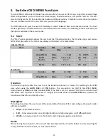
  (EBU/SMPTE/AUTO): There are two different audio standards available for selection. The user can 

either select the EBU or SMPTE standard. By selecting AUTO allows the device to automatically detect the 

audio standard.  
 

GPI Out 

This allows the user to perform GPI configuration. After turning on the GPI, select the GPI 

mode

, which is 

either level or pulse. The pulse width can also be configured in the sub-option 

Width

 (1-9). GPI out can 

then be assigned to one of Inputs 1-6 and the 

delay

 can be set to between 1 and 99. This feature could be 

used to trigger playback from an external playback device such as Datavideo’s NVP-20 or HRS-30 unit. 
 

Multiviewer 

AutoNum: The Multiview windows can be automatically numbered, and this sub-option turns ON/OFF 

automatic numbering. 
Label Inf: This sub-option turns ON/OFF Label information. Input label is followed by information which 

describes the input as still, live or frozen image. 
Trns Lab: This sub-option turns ON/OFF Label Transparency. Once enabled, the background of the label is 

then turned from a solid colour to transparent.


5.8


Stills 

Still allows the user to load images from the memory, save images to the memory, and save the images 

captured. 

Advanced Mode 

Stills


Load Still 

Load


Still Num 

13 

Input 5


Thumbnail 

Picture - 1


Thumbnail Picture  Thumbnail Picture 

+ 1 


Save Still 

Save


Input 5


Still Num 

13 


Freeze 

Still 

Live 

Still 


Still 

Still 

Live 


Basic Mode 

Stills


Load Still 

Load


Still Num 

13 

Input 5


Thumbnail 

Picture - 1


Thumbnail Picture  Thumbnail Picture 

+ 1 


Save Still 

Save


Input 5


Still Num 

13 


Load Still 

Upon selecting “Load Still”, the user can then choose the memory location from which the still image is 

loaded. The following are the destinations to which the still image can be loaded:  


Input 6 


Input 5 


Input 4 


Input 3 


Input 2 


Input 1 

Summary of Contents for HS-1200

Page 1: ...HS 1200 HD 6 CHANNEL PORTABLE VIDEO STUDIO Instruction Manual ...

Page 2: ... Transition GRAB 13 Wipe Border Setting 13 Wipe Transition Selection 14 Program Preview Source Row 14 Transition Effect 15 Audio Control 16 3 2 MONITOR CONTROL PANEL 17 4 SWITCHER OSD MENU OVERVIEW 19 5 SWITCHER OSD MENU FUNCTIONS 25 5 1 START 25 Transition 25 Wipe Effects 25 Border 25 Position 26 Matte 26 5 2 KEYER 26 Keyer Control 26 Key Source 27 Fill Source 27 Mask 27 5 3 CHROMA 27 Keyer 27 CK...

Page 3: ...only At all times Datavideo Technologies will try to give correct complete and suitable information However Datavideo Technologies cannot exclude that some information in this manual from time to time may not be correct or may be incomplete This manual may contain typing errors omissions or incorrect information Datavideo Technologies always recommend that you double check the information in this ...

Page 4: ...re of the type of power available consult your Datavideo dealer or your local power company 8 Do not allow anything to rest on the power cord Do not locate this unit where the power cord will be walked on rolled over or otherwise stressed 9 If an extension cord must be used with this unit make sure that the total of the ampere ratings on the products plugged into the extension cord do not exceed t...

Page 5: ...t covered under warranty Viruses and malware infections on the computer systems are not covered under warranty Any errors that are caused by unauthorized third party software installations which are not required by our computer systems are not covered under warranty All mail or transportation costs including insurance are at the expense of the owner All other claims of any nature are not covered A...

Page 6: ...onserve natural resources and ensure that it is recycled in a manner that protects human health and the environment For more information about where you can drop off your waste equipment for recycling please contact your local city office your household waste disposal service or the shop where you purchased the product CE Marking is the symbol as shown on the left of this page The letters CE are t...

Page 7: ...the worship education and AV market 1 1 Features Video System 6 video inputs compatible with 1920x1080i video format 4 HD SDI and 2 HDMI video inputs 2 HD SDI video outputs and each output can be switched in the menu as PROGRAM with DSK Clean PROGRAM without DSK Clean PREVIEW without DSK MULTISCREEN Input 1 6 1 HDMI video output only for multiviewer Keyers for configuring DSK luma key chroma key a...

Page 8: ...1 4 11 Tally Signal Output 6 HD SDI Video Output 1 2 12 USB Firmware Upgrade Port 2 1 Rear Panel Connections 1 POWER SWITCH Switches the power On Off 2 DC Power Input Connect the supplied 12V 5A PSU to this 4 PIN XLR socket 3 Monitor HDMI IN External Video Input The HS 1200 provides a useful connection for confidence monitoring of HDMI sources on location Connect one external HDMI input source for...

Page 9: ... the Switcher Menu 6 SDI Video Output 1 2 The BNC output connector is a user defined SDI output Note Please set the OUTPUT SOURCE in the Switcher Menu 7 HDMI Video Ouput Multiview ONLY Connect the HDMI output port to an external monitor on which the Multiview is displayed Note This is NOT a user defined output which is used for Multiview Display ONLY The limitations of this port are 1 No audio out...

Page 10: ...ally Signal Output Sends Red and Green tally signals to each channel Red indicates On Air and Green indicates next camera source 12 USB Firmware Upgrade Port Connect the USB drive containing the latest firmware files to this port and start the firmware upgrade process on the OSD MENU Note Please refer to the section on Firmware Update Procedure for firmware upgrade details ...

Page 11: ...uttons 1 6 allow the user to recall and load previously saved switcher settings SHIFT There are 12 user memory locations Under normal circumstances Buttons USER 1 to 6 represent user memory locations 1 to 6 To load settings saved in locations 7 to 12 to buttons USER 1 6 simply press the SHIFT button SAVE User Memory Save The SAVE button saves the current switcher settings To save keep holding down...

Page 12: ...m any setting that has been changed To Exit simply press the MENU button again Keyer Selection Key 1 PGM enables key 1 on the Multi view and PGM output Key 2 PGM enables key 2 on the Multi view and PGM output DSK 1 PGM enables DSK 1 on the Multi view and PGM output DSK 2 PGM enables DSK 2 on the Multi view and PGM output Key 1 PVW enables key 1 on the Multi view and PVW output Key 2 PVW enables ke...

Page 13: ...esponds to the selected keyer Key 1 Key 2 DSK 1 DSK 2 DSK AUTO Auto DSK transition function either transitions DSK 1 or DSK 2 individually or transitions DSK 1 and DSK 2 simultaneously PIP Effect PIP enables the PIP key mode PIP LITE enables the PIP LITE key mode Background Transition GRAB TRANS BG enables Background Transition between Program Preset GRAB grabs the current Program video image Wipe...

Page 14: ...orner Box Wipe from Centre to outside edges Diamond Wipe from Centre to outside edges Circle Wipe from Centre to outside edges Cross Wipe from Centre to outside edges Heart Wipe from Centre to outside edges Program Preview Source Row The Program row of buttons is the active channel this is the live output The active channel will appear as the Program Output You can switch or CUT from one video sou...

Page 15: ...sing the rate of transition or time taken when using the AUTO TAKE button Transition Speed 1 2 and 3 Button 1 12 frame duration 2 25 and 3 50 at 1080i50 Button 1 15 frame duration 2 30 and 3 60 at 1080i60 PVW TRANS Transition shown on PVW only MIX This button enables MIX transition effect WIPE This button enables WIPE transition effect The WIPE button must be selected when a wipe effect transition...

Page 16: ...e selected transition wipe or MIX will also be used The timing of the transition is set by the chosen Speed button Audio Control Headphone Socket 6 3mm Stereo Headphone Socket for conventional headphones MUTE This button mutes the headphone audio Headphone Volume Control Controls Headphone or Headset volume level ...

Page 17: ...lugged into the MONITOR HDMI IN port BLUE Press this button to eliminate the red and green component of input signals Only the blue component of an input is displayed on the screen This allows adjustments of chroma and phase Phase adjustment is effective with NTSC signals MV Press this button to set the Monitor to MULTIVIEW mode PGM Press this button to set the Monitor to PROGRAM view PTN When pre...

Page 18: ...t ratio of the source pixels to fill the screen The ZOOM button allows you to toggle the Pixel Zoom feature between zoom x1 x2 x4 and x8 Menu Navigation Buttons Display and navigate the set up menus See Monitor Menu Options for more details Aspect Ratio Button Sets the Aspect Ratio to 16 9 4 3 Volume Control Adjusts the speaker headphone volume up down MUTE Mutes the audio from the internal speake...

Page 19: ... Clip Wipe Mix Wipe Effects Wipe Wipe Effect Presets Soft Border Softness Width Border Width Border Luma Border Color Luma Sat Border Color Saturation Hue Border Color Hue Position X Horizontal Position Y Vertical Position Matte Luma Background Matte Luma Sat Background Matte Saturation Hue Background Matte Hue Keyer Keyer DSK 2 DSK 1 Key 2 Key 1 Keyer Selection Keyer Ctrl Chroma Luma Linear Type ...

Page 20: ...Calculation of the best Hue Luma values for the current Keyer source Hue Parameter for color of the chroma key Luma Parameter for luma of the chroma key K Range Setting the range of colors that match the background color to be keyed K Fgnd Adjusts the performance of the chroma key in dark or black areas K Bgnd Adjusts the performance of the chroma key in light or white areas Hi Light Boosts the fo...

Page 21: ...P Border Color Hue Width PIP Border Width Crop Left Left Edge of the Crop Right Right Edge of the Crop Size Size of the Crop Top Top Edge of the Crop Bot Bottom Edge of the Crop Inputs Input 1 Black Black Level White White Level Chrom Chroma Level Input 2 Black Black Level White White Level Chrom Chroma Level Input 3 Black Black Level White White Level Chrom Chroma Level Input 4 Black Black Level ...

Page 22: ...put 3 Input 2 Input 1 OFF 4 Input 6 Input 5 Input 4 Input 3 Input 2 Input 1 OFF 5 Input 6 Input 5 Input 4 Input 3 Input 2 Input 1 OFF 6 Input 6 Input 5 Input 4 Input 3 Input 2 Input 1 OFF Outputs Output SDI1 SDI2 HDMI 17 3 Built in Monitor Input 6 Input 5 Input 4 Input 3 Input 2 Input 1 CLN PVW Clean PVW CLN PGM Clean PGM PG DSK PVW PGM MultiV Multi view ...

Page 23: ... Input3 Input2 Input1 Thumbnail Picture 1 Preview of the previous image Thumbnail Picture Preview of the image to be loaded Thumbnail Picture 1 Preview of the next image Save Still Save Pressing this button saves the selected still picture Source Input6 Input5 Input4 Input3 Input2 Input1 Still Memory Location 0 500 Freeze 1 Sets the Frame store mode of Input 1 to Clip Still Freeze Live 2 Sets the ...

Page 24: ...ion Auto Save ON OFF Automatically saves the last settings before the machine is shut down once turned ON auto save also occurs upon every Still Load Factory Def Reset Factory Default Reset loads the default configuration from memory point 0 for all configuration options except for the Setup Reset Names Resets the Multiviewer labels to the default settings Language English Traditional Chinese Simp...

Page 25: ...pe 1 Soft 0 Width 0 Border Luma 100 Sat 80 Hue 178 Position X 0 Y 0 Matte Luma 100 Sat 80 Hue 0 Basic Mode Start Transition M E 60 DSK 60 FTB 60 Wipe Effects Wipe 1 Soft 0 Width 0 Transition The transition option allows the user to set the transition duration in frames for switching to the PGM view when using the AUTO DSK and FTB buttons The sub options are AUTO Mix Effect M E Downstream Key DSK a...

Page 26: ...ect Self if only one source is enabled for the keyer which is Key source and select Split if two sources are enabled for the keyer which are Key and Fill sources You may also select P in P or P in P Lite to apply the keying effect to the P in P window Please note If Luma is selected fine tune the Luma Keyer parameters Lift Gain and Opac in the Keyer option If Chroma is selected fine tune the Chrom...

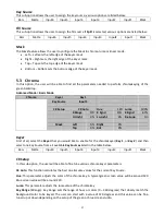
Page 27: ...tup CK Auto Hue 120 Luma 100 KRange 170 K Fgnd 15 K Bgnd 67 Hi Light 0 Lo Light 0 Bg Supp On Mask Left 0 Right 0 Top 0 Bot 0 Keyer First of all select the Keyer that you would like to enable for the chromakeyer Key 1 or Key 2 and then select one Key Source from all available Key Sources listed in the table below Bars Matte Input6 Input5 Input4 Input3 Input2 Input1 Black CK Setup In this sub option...

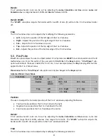
Page 28: ...on if the user selects P in P in the Keyer Ctrl sub option of the Keyer option P in P Scr sub option indicates the keyer enabled for P in P In our example below the Key 1 keying effect will be applied to the P in P window Please note that the P in P Scr sub option can only be changed in the Keyer option Advanced Mode Basic Mode P in P P in P Src Key 1 Position X 20 Y 10 Size 50 Border Luma 0 Sat 0...

Page 29: ...ects P in P Lite in the Keyer option P in P Keyer sub option will indicate the keyer enabled for P in P Lite In our example below the Key 1 keying effect will be applied to the P in P Lite window Please note that the P in P Keyer sub option can only be changed in the Keyer option Advanced Mode Basic Mode P in P Lite P in P Keyer Key 1 Position X 22 Border Luma 100 Sat 80 Hue 0 Width 2 Crop Left 32...

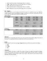
Page 30: ...1 0 Freeze 1 Still 2 Live 3 Still 4 Still 5 Still 6 Live Crosspoint 1 Input 1 2 Input 2 3 Input 3 4 Input 4 5 Input 5 6 Input 6 Basic Mode Inputs Freeze 1 Still 2 Live 3 Still 4 Still 5 Still 6 Live Crosspoint 1 Input 1 2 Input 2 3 Input 3 4 Input 4 5 Input 5 6 Input 6 Input 1 4 By selecting the corresponding input Inputs 1 4 the user will then be allowed to configure the colour of the inputs 1 4 ...

Page 31: ...owing Input 6 Input 5 Input 4 Input 3 Input 2 Input 1 CLN PVW Clean PVW CLN PGM Clean PGM PG DSK PVW PGM MultiV Multi view In addition to selecting your output source you are also allowed to set two different resolutions for the 17 3 built in monitor The two available resolutions are 1080i and 1080p Audio The Audio sub option for the SDI and HDMI outputs allows the user to individually turn ON OFF...

Page 32: ... turns ON OFF Label information Input label is followed by information which describes the input as still live or frozen image Trns Lab This sub option turns ON OFF Label Transparency Once enabled the background of the label is then turned from a solid colour to transparent 5 8 Stills Still allows the user to load images from the memory save images to the memory and save the images captured Advanc...

Page 33: ...ive 5 9 User Mems In this option the user is allowed to load previously saved settings and save the currently configured settings Advanced Mode Basic Mode User Mems Load Mem Memory 1 Load Save Mem Memory 1 Save Load Memory Use the up down arrow to scroll to the desired memory location 1 999 and load the saved setting by selecting Load The user can also press one of the USER memory shortcut buttons...

Page 34: ...ode Menu Position Menu Position gives the user ability to select several positions for the Menu area on the Screen The current options are Centre Top Left Right and Bottom Standard This option allows the user to choose the appropriate output resolution such as 1080i 50 Once done simply select Save Setup to confirm the selected output resolution The available resolutions are 1080i 50 59 94 60 720p ...

Page 35: ...6 to their default settings Language The available languages for OSD menu are English Traditional Chinese and Simplified Chinese Software This option is only available when the USB storage device containing the latest firmware file is inserted Select Upgrade to start the firmware upgrade process Refer to the FIRMWARE UPDATE section for more details At the bottom of the menu you will be able to vie...

Page 36: ...d within the switcher s non volatile memory Main Options Sub Options Parameters Parameters MAIN ADJUST BRIGHTNESS 0 100 CONTRAST 0 100 SHARPNESS 0 100 SATURATION 0 100 TINT 0 100 BACK LIGHT 0 100 NR HIGH MID LOW OFF MPEG NR HIGH LOW OFF VOLUME 0 100 EXIT COLOR 6500 9300 7500 USER COLOR RED 0 100 GREEN 0 100 BLUE 0 100 EXIT SCAN SETTING UNDER SCAN full image OVER SCAN cropped image INFORMATION H FR...

Page 37: ...as this could result in a non responsive unit 1 Locate the FW Upgrade USB port on the front panel of the HS 1200 2 Insert the USB stick that contains the latest firmware to the FW upgrade port 3 Power on the device and the device should automatically detect the connected USB storage device 4 Press the MENU button on the control panel to open the menu on the monitor screen 5 Press the down arrow bu...

Page 38: ... Power is supplied by the HS 1200 and is less than 5V DC This GPI socket can also be used as a socket to trigger record or playback events with other equipment such as the Datavideo HDR 70 recorder SAFETY FIRST The cabling required needs to be designed specifically to connect the HS 1200 to the chosen record or playback device as they are not all the same The cabling required can be made by yourse...

Page 39: ...iew 1 Open collector output Tally output of input video Preview 1 4 RCOM GND Ground Ground 5 Program 4 Open collector output Tally output of input video Program 4 6 Program 2 Open collector output Tally output of input video Program 2 7 Program 6 Open collector output Tally output of input video Program 6 8 Preview 2 Open collector output Tally output of input video Preview 2 9 GND Ground Ground 1...

Page 40: ...40 10 Dimensions All measurements in millimetres mm ...

Page 41: ...M PREVIEW w o DSK MULTISCREEN Input 1 6 Audio Indicator on Multi view Y output 2CH Computer Output Ethernet Motion JPEG Out Control Panel Connection RS 232 Tally Out Y GPI Two mode Level Pulse trigger selectable Speaker Volume Control Control Knob Software Updates Ethernet Monitor LCD Display 17 3 TFT LCD Resolution RGB 1600 x 900 pixel Aspect Ratio 4 3 and 16 9 selectable LED Life time 12 000 hrs...

Page 42: ...low video Master gain control HD Down Conversion N A Extras Upstream Keyers 2 M E Keyer PIP Downstream Keyers 2 Linear Luma Keyers 4 Chroma Keyers 2 M E Keyer PIP Pattern Generators Color Bar PIP 1 XPT Y Frame store Any Input can be used as Frame store 8 Still frames stored in local frame buffers for instant access Control Panel Compatibility Use PC via Ethernet Control Panel Input Voltage 8V 17V ...

Page 43: ...inan City Shandong Province China Tel 86 531 8607 8813 E mail service datavideo cn China Jinan Datavideo France s a r l Cité Descartes 1 rue Albert Einstein Champs sur Marne 774477 Marne la Vallée cedex 2 Tel 33 1 60370246 Fax 33 1 60376732 E mail info datavideo fr France Datavideo Hong Kong Ltd G F 26 Cross Lane Wanchai Hong Kong Tel 852 2833 1981 Fax 852 2833 9916 E mail info datavideo com hk Ho...

Reviews: