23
These concepts are depicted in the PodWare application as in the following example of a 2-‐way
Module:
A
Snapshot
is a device-‐wide representation of most of the settings in the device. This is represented
as four Input Component numbers, eight Output Component numbers, plus a number of machine-‐
centric settings such as routing and Input/Output Analogue/Digital selection etc.
Device
Settings
Input A component number
Input B component number
Input C component number
Input D component number
Output 1 component number
Output 2 component number
Output 3 component number
Output 4 component number
Output 5 component number
Output 6 component number
Output 7 component number
Output 8 component number
Navigation
Parameter navigation and adjustment on the DNA Pro is very straightforward. There is no concept of
drilling down deeper into hidden menus; every parameter is accessible by simply scrolling across a
‘map’ of parameter pages which can be thought of as placed on a 2-‐dimensional grid. Horizontally
across the width of the grid are the various channels, and vertically up and down the grid are the
parameter pages for each section of processing.
To view a parameter, repeatedly press the desired <
INPUT
> or <
OUTPUT
> channel button until the
desired channel is reached. Then repeatedly press the up <
p
> and down <
q
> buttons to scroll
through the processing parameters for the selected input/output.
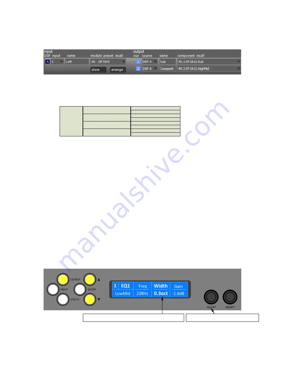
Two encoders allow you to select and adjust a parameter. Often, several parameters will be shown
in various zones on the display. To select a parameter for adjustment, turn the right-‐most encoder
such that the parameter you wish to adjust is highlighted. Then turn the leftmost encoder to adjust
the value of that parameter. Turning this encoder clockwise will increase the value of a parameter,
or anticlockwise will decrease it. The encoders are velocity-‐sensitive so turning an encoder rapidly
will cause the action to ‘accelerate’, so the value changes more rapidly.
Turn the ADJUST encoder to change its value.
Turn the SELECT encoder to highlight the zone you wish to adjust.
Summary of Contents for DNA 10K4
Page 12: ...12 INSTALLATION INSTRUCTIONS Mechanical Installation 431 360 37 482 88...
Page 40: ...40 Processing Block Diagram...
Page 43: ...43 EQ and Filter Response Graphs...
Page 44: ...44...
Page 45: ...45...
Page 46: ...46...


