


M
3
96 97
99
98
91 92 93 95
50
12
L1 L2
L1
PE
L3
W PE
V
U
F1
L2
L3
N
PE
18
53
37
55
20
32
33
39
24 Vdc
130BA174.10
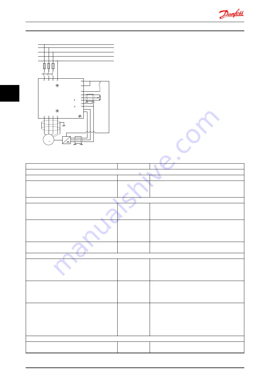
Illustration 4.8 Example - Speed Control Connections
The following must be programmed in order shown (see
explanation of settings in the
FCD 302 Programming Guide,
MG04G
)
In the list it is assumed that all other parameters and
switches remain at their default setting.
Function
Parameter no.
Setting
1) Make sure the motor runs properly. Do the following:
Set the motor parameters using name plate data
1-2*
As specified by motor name plate
Have the frequency converter makes an Automatic
Motor Adaptation
1-29 Automatic
Motor Adaptation
(AMA)
[1] Enable complete AMA
2) Check the motor is running and the encoder is attached properly. Do the following:
Press the “Hand On” LCP key. Check that the motor is
running and note in which direction it is turning
(henceforth referred to as the “positive direction”).
Set a positive reference.
Go to
16-20 Motor Angle
. Turn the motor slowly in the
positive direction. It must be turned so slowly (only a
few RPM) that it can be determined if the value in
16-20 Motor Angle
is increasing or decreasing.
16-20 Motor Angle
N.A. (read-only parameter) Note: An increasing value
overflows at 65535 and starts again at 0.
If
16-20 Motor Angle
is decreasing then change the
encoder direction in
5-71 Term 32/33 Encoder Direction
.
5-71 Term 32/33
Encoder Direction
[1] Counter clockwise (if
16-20 Motor Angle
is decreasing)
3) Make sure the drive limits are set to safe values
Set acceptable limits for the references.
3-02 Minimum
Reference
3-03 Maximum
Reference
0 RPM (default)
1500 RPM (default)
Check that the ramp settings are within drive capabilities
and allowed application operating specifications.
3-41 Ramp 1 Ramp
up Time
3-42 Ramp 1 Ramp
Down Time
default setting
default setting
Set acceptable limits for the motor speed and frequency. 4-11 Motor Speed
Low Limit [RPM]
4-13 Motor Speed
High Limit [RPM]
4-19 Max Output
Frequency
0 RPM (default)
1500 RPM (default)
60 Hz (default 132 Hz)
4) Configure the Speed Control and select the Motor Control principle
Activation of Speed Control
1-00 Configuration
Mode
[1] Speed closed loop
Application Examples
VLT
®
Decentral Drive FCD 302
54
MG04H102 - VLT
®
is a registered Danfoss trademark
4
4