
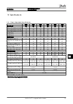
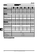
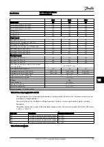


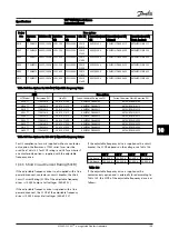

10.2 General Technical Data
Line power supply (L1, L2, L3)
Supply voltage
380–480 V
±
10%, 525–690 V
±
10%
AC line voltage low/line voltage drop-out:
During low AC line voltage or a line drop-out, the adjustable frequency drive continues until the intermediate circuit voltage
drops below the minimum stop level, which corresponds typically to 15% below the adjustable frequency drive's lowest rated
supply voltage. Power-up and full torque cannot be expected at AC line voltage lower than 10% below the adjustable frequency
drive's lowest rated supply voltage.
Supply frequency
50/60 Hz ±5%
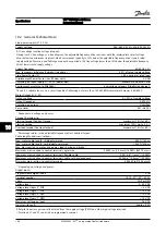
Max. temporary imbalance between line phases
3.0% of rated supply voltage
True Power Factor (λ)
≥0.9 nominal at rated load
Displacement Power Factor (cos Φ) near unity
(>0.98)
Switching on input supply L1, L2, L3 (power-ups)
maximum one time/2 min
Environment according to EN60664-1
overvoltage category III/pollution degree 2
The unit is suitable for use on a circuit capable of delivering not more than 100,000 RMS symmetrical Amperes, 480/600 V
Motor Output (U, V, W)
Output voltage
0–100% of supply voltage
Output frequency
0–590 Hz
*
Switching on output
Unlimited
Ramp times
0.01–3,600 s
*
Dependent on voltage and power
Torque Characteristics
Starting torque (Constant torque)
maximum 110% for 60 s
*
Starting torque
maximum 135% up to 0.5 s*
Overload torque (Constant torque)
maximum 110% for 60 s
*
*)
Percentage relates to the adjustable frequency drive's nominal torque
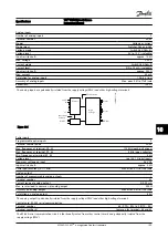
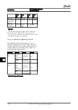
Cable lengths and cross-sections
Max. motor cable length, shielded/armored
500 ft [150 m]
Max. motor cable length, unshielded/unarmored
1,000 ft [300 m]
Max. cross-section to motor, line power, load sharing and brake
*
Maximum cross-section to control terminals, rigid wire
0.0023 in
2
[1.5 mm
2
]/16 AWG (2x0.75 mm
2
)
Maximum cross-section to control terminals, flexible cable
0.0016 in
2
[1 mm
2
]/18 AWG
Maximum cross-section to control terminals, cable with enclosed core
0.0008 in
2
[0.5 mm
2
]/20 AWG
Minimum cross-section to control terminals
0.00039 in2 [0.25 mm2]
*)
Depending on voltage and power.
Digital inputs
Programmable digital inputs
4 (6)
Terminal number
18, 19, 27
1)
, 29
1)
, 32, 33
Logic
PNP or NPN
Voltage level
0–24 V DC
Voltage level, logic '0' PNP
<5 V DC
Voltage level, logic '1' PNP
>10 V DC
Voltage level, logic '0' NPN
>19 V DC
Voltage level, logic '1' NPN
<14 V DC
Maximum voltage on input
28 V DC
Input resistance, R
i
approx. 4 kΩ
All digital inputs are galvanically isolated from the supply voltage (PELV) and other high-voltage terminals.
1)
Terminals 27 and 29 can also be programmed as output.
Specifications
VLT
®
HVAC Drive D-Frame
Instruction Manual
10-4
MG16D222 - VLT
®
is a registered Danfoss trademark
10
10


