


•
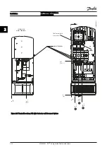
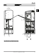
Connector 1 provides four programmable digital
input terminals, two additional digital terminals
programmable as either input or output, a 24 V
DC terminal supply voltage, and a common for
optional customer-supplied 24 V DC voltage
•
Connector 2 terminals (+)68 and (-)69 are for an
RS-485 serial communications connection
•
Connector 3 provides two analog inputs, one
analog output, 10 V DC supply voltage, and
commons for the inputs and output
•
Connector 4 is a USB port available for use with
the MCT 10 Set-up Software
•
Also provided are two Form C relay outputs that
are in various locations depending upon the
adjustable frequency drive configuration and size
•
Some options available for ordering with the unit
may provide additional terminals. See the manual
provided with the equipment option
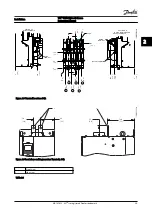
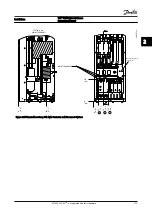
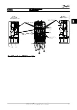
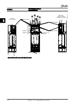
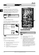
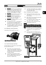
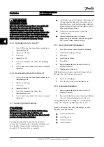
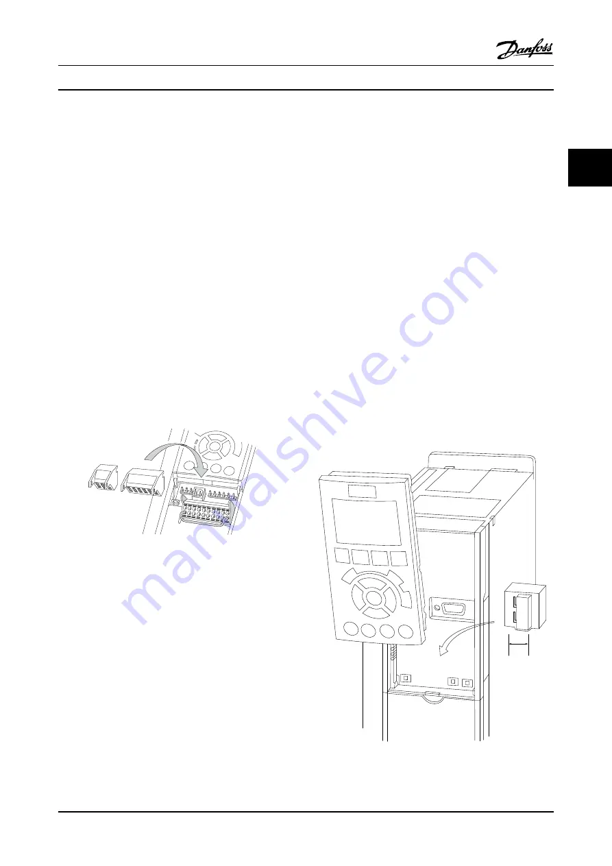
2.5.5 Wiring to Control Terminals
Terminal plugs can be removed for easy access.
130B
T306.10
Figure 2.30 Removal of Control Terminals
2.5.6 Control Terminal Functions
Adjustable frequency drive functions are commanded by
receiving control input signals.
•
Each terminal must be programmed for the
function it will be supporting in the parameters
associated with that terminal. See
and
for terminals and
associated parameters.
•
It is important to confirm that the control
terminal is programmed for the correct function.
See
for details on accessing
parameters and programming.
•
The default terminal programming is intended to
initiate adjustable frequency drive functioning in
a typical operational mode
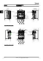
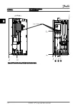
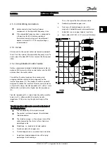
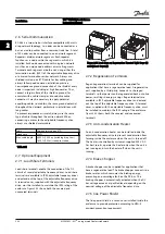
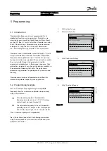
2.5.6.1 Terminal 53 and 54 Switches
•
Analog input terminals 53 and 54 can select
either voltage (-10 to 10 V) or current (0/4–20
mA) input signals
•
Remove power to the adjustable frequency drive
before changing switch positions.
•
Set switches A53 and A54 to select the signal
type. U selects voltage, I selects current
•
The switches are accessible when the LCP has
been removed (see
).
NOTE!
Some option cards available for the unit may cover these
switches and must be removed to change switch settings.
Always remove power to the unit before removing option
cards.
•
Terminal 53 default is for a speed reference signal
in open-loop set in
16-61 Terminal 53 Switch
Setting
•
Terminal 54 default is for a feedback signal in
closed-loop set in
16-63 Terminal 54 Switch Setting
130B
T310.10
1
2
N O
VLT
BUS TER.
OFF-ON
A53 A54
U- I U- I
Figure 2.31 Location of Terminals 53 and 54 Switches and Bus
Termination Switch
Installation
VLT
®
HVAC Drive D-Frame
Instruction Manual
MG16D222 - VLT
®
is a registered Danfoss trademark
2-23
2
2


