
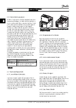


When not using the SAS, enter data in accordance with
the following procedure.
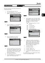
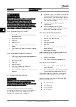
1.
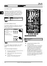
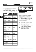
Press [Main Menu] twice on the LCP.
2.
Press the navigation keys to scroll to parameter
group
0-** Operation/Display
and press [OK].
130BP066.10
1107 RPM
0 - ** Operation/Display
1 - ** Load/Motor
2 - ** Brakes
3 - ** Reference / Ramps
3.84 A
1 (1)
Main Menu
Figure 3.1
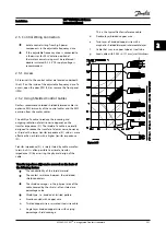
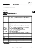
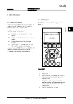
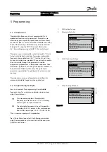
3.
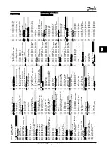
Press the navigation keys to scroll to parameter
group
0-0* Basic Settings
and press [OK].
0-
**
Operation / Display
0.0%
0-0
*
Basic Settings
0-1
*
Set-up Opperations
0-2
*
LCP Display
0-3
*
LCP Custom Readout
0.00A
1(1)
130BP087.10
Figure 3.2
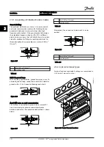
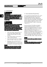
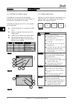
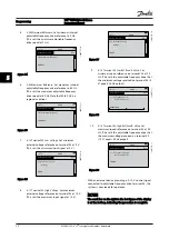
4.
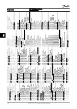
Press the navigation keys to scroll to
0-03 Regional Settings
and press [OK].
0-0
*
Basic Settings
0.0%
0-03 Regional Settings
[0] International
0.00A
1(1)
130BP088.10
Figure 3.3
5.
Press the navigation keys to select
International
or
North America
as appropriate and press [OK].
(This changes the default settings for a number
of basic parameters. See
for a complete list.)
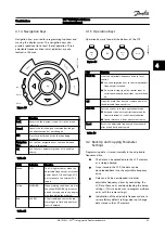
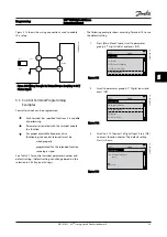
6.
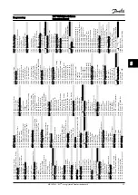
Press [Quick Menu] on the LCP.
7.
Press the navigation keys to scroll to parameter
group
Q2 Quick Set-up
and press [OK].
130BB847.10
Q1 My Personal Menu
Q2 Quick Setup
Q5 Changes Made
Q6 Loggings
13.7% 13.0A 1(1)
Quick Menus
Figure 3.4
8.
Select language and press [OK]. Then enter the
motor data in
1-20 Motor Power [kW]
/
1-21 Motor
Power [HP]
to
1-25 Motor Nominal Speed
. The
information can be found on the motor
nameplate.
•
1-20 Motor Power [kW]
or
1-21 Motor
Power [HP]
•
1-22 Motor Voltage
•
1-23 Motor Frequency
•
1-24 Motor Current
•
1-25 Motor Nominal Speed
130B
T772.10
Q2
0.0 Hz 0.00kW 1(1)
Motor Setup
1 - 21 Motor Power [kW]
4.0
kW
Figure 3.5
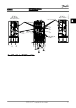
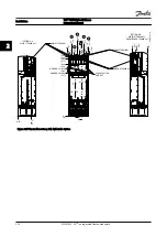
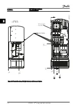
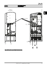
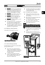
9.
A jumper wire should be in place between
control terminals 12 and 27. If this is the case,
leave
5-12 Terminal 27 Digital Input
at factory
default. Otherwise select
No Operation
. For
adjustable frequency drives with an optional
bypass, no jumper wire is required.
10.
3-02 Minimum Reference
11.
3-03 Maximum Reference
12.
3-41 Ramp 1 Ramp-up Time
13.
3-42 Ramp 1 Ramp-down Time
14.
3-13 Reference Site
. Linked to Hand/Auto* Local
Remote.
This concludes the quick set-up procedure. Press [Status]
to return to the operational display.
Startup and Commissioning
VLT
®
HVAC Drive D-Frame
Instruction Manual
MG16D222 - VLT
®
is a registered Danfoss trademark
3-3
3
3


