


2.6 Serial Communication
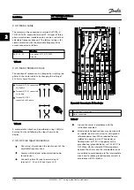
RS-485 is a two-wire bus interface compatible with multi-
drop network topology, i.e., nodes can be connected as a
bus, or via drop cables from a common trunk line. A total
of 32 nodes can be connected to one network segment.
Repeaters divide network segments. Each repeater
functions as a node within the segment in which it is
installed. Each node connected within a given network
must have a unique node address across all segments.
Terminate each segment at both ends, using either the
termination switch (S801) of the adjustable frequency drive
or a biased termination resistor network. Always use
shielded twisted pair (STP) cable for bus cabling, and
always follow good common installation practice.
Low-impedance ground connection of the shield at every
node is important, including at high frequencies. Thus,
connect a large surface of the shield to ground, for
example with a cable clamp or a conductive cable
connector. It may be necessary to apply potential-
equalizing cables to maintain the same ground potential
throughout the network. particularly in installations with
long cables.
To prevent impedance mismatch, always use the same
type of cable throughout the entire network. When
connecting a motor to the adjustable frequency drive,
always use shielded motor cable.
Cable
Shielded twisted pair (STP)
Impedance
120
Ω
Max. cable length
4,000 ft [1,200 m] (including drop lines)
1,650 ft [500 m] station-to-station
Table 2.11
2.7 Optional Equipment
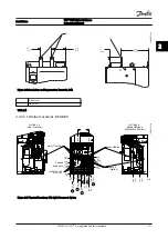
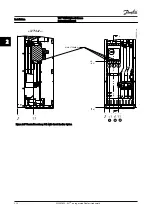
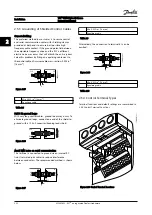
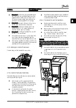
2.7.1 Load Share Terminals
Load share terminals enable the connection of the DC
circuits of several adjustable frequency drives. Load share
terminals are available in IP20 adjustable frequency drives
and extend out the top of the adjustable frequency drive.
A terminal cover, supplied with the adjustable frequency
drive, must be installed to maintain the IP20 rating of the
enclosure.
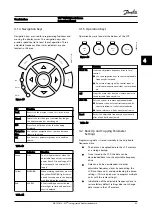
shows both the covered and
uncovered terminals.
130BC547.10
Figure 2.32 Load Share or Regeneration Terminal with Cover (L)
and without Cover (R)
2.7.2 Regeneration Terminals
Regen (regeneration) terminals can be supplied for
applications that have a regenerative load. A regenerative
unit, supplied by a third party, connects to the regen
terminals so that power can be regenerated back onto line
power, resulting in energy savings. Regen terminals are
available in IP20 adjustable frequency drives and extend
out the top of the adjustable frequency drive. A terminal
cover, supplied with the adjustable frequency drive, must
be installed to maintain the IP20 rating of the enclosure.
shows both the covered and uncovered
terminals.
2.7.3 Anti-condensation Heater
An anti-condensation heater can be installed inside the
adjustable frequency drive to prevent condensation from
forming inside the enclosure when the unit is turned off.
The heater is controlled by customer-supplied 230 V AC.
For best results, operate the heater only when the unit is
not running and turn the heater off when the unit is
running.
2.7.4 Brake Chopper
A brake chopper can be supplied for applications that
have a regenerative load. The brake chopper connects to a
brake resistor, which consumes the braking energy,
preventing an overvoltage fault on the DC bus. The
braking chopper is automatically activated when the DC
bus voltage exceeds a specified level, depending on the
nominal voltage of the adjustable frequency drive.
2.7.5 line Power Shield
The line power shield is a Lexan cover installed inside the
enclosure to provide protection according to VBG-4
accident-prevention requirements.
Installation
VLT
®
HVAC Drive D-Frame
Instruction Manual
2-24
MG16D222 - VLT
®
is a registered Danfoss trademark
2
2


