Decentral Solutions
Installation, FCD
300
T73 version with motor plug and sensor plugs
Version is supplied from Danfoss with wiring as shown
T63 version with service switch (no motor plug)
MG.90.F2.22 - VLT is a registered Danfoss trademark
81
Page 1: ...al warning 42 Safety regulations 42 Warning against unintended start 42 Avoiding DMS damage 42 Mechanical details DMS 300 43 Description 43 General layout 43 Construction 43 Tools required 43 Wall mounting 43 Motor mounting 43 Ventilation 44 Electrical connections DMS 300 45 Power Wiring 45 Power factor correction 45 Control Wiring 45 Motor thermistors 47 Serial communication 47 Grounding 47 High ...
Page 2: ...Profibus Connectivity 59 Profibus DP Slave 6 E DC 24 V 4 A DC 24 V 1A 59 Table of bits in control and status word 60 Profibus connector PCB 4 x M12 60 Profibus address setting DIP switch SW3 61 Introduction to FCD 300 62 Software version 62 High voltage warning 63 These rules concern your safety 63 Warning against unintended start 63 Technology 64 CE labeling 67 Installation FCD 300 69 Mechanical ...
Page 3: ...he LCP 2 control unit option 93 Parameter selection 97 Operation Display 99 Setup configuration 99 Load and Motor 108 DC Braking 113 Motortype par 147 FCD 300 117 References Limits 118 Handling of references 118 Reference function 122 Inputs and outputs 127 Special functions 137 PID functions 139 Handling of feedback 141 Serial communication for FCD 300 149 Control Word according to FC protocol 15...
Page 4: ...rmonics 183 Power factor 184 Emission test results according to generic standards and PDS product standard 185 Immunity test result according to Generic standards PDS product standards and basic standards 185 Aggressive environments 187 Cleaning 187 Status messages 189 Warnings alarm messages 189 Warning words extended status words and alarm words 192 General technical data 194 Technical data line...
Page 5: ...abinet rather than several places in the factory Continuing improvements in semi conductors and related technologies such as fieldbus technology now again makes it feasible to consider installing drives close to the motors achieving the benefits of decentralized installation without the disadvantages from the first oil filled variable frequency drives Development of automation in industry is based...
Page 6: ...lligence and there are areas particularly in the process industry with areas such as explosion protection where centralized cabinets continue to be the preferred solution Centralized versus decentralized installations Placing the advanced and reliable electronics needed to ensure a smooth responsive and economical operation of the motor next to or on the motor facilitates modularization and reduce...
Page 7: ...otential is considerable as will be demonstrated by the following example The figure illustrates an installation with motors distributed in a number of rows with several motors in each as is the situation in for example parallel bottling or baking lines in the Food and Beverage industry This example shows the need for power cables from the centrally placed drives to the motors Centralized installa...
Page 8: ...es of 1 5 HP 1 5 kW motors taking the cable dimensioning into account showed the following saving potential in cables and terminations Cable terminations are reduced from 455 to 352 EMC cable terminations are reduced from 364 to 182 by using motor controls with integrated service switches Power cable length reduced from 21 220 ft 6468m to 3870ft 1180m a reduction of 17 350ft 5288m and it is conver...
Page 9: ... minimize lead time Even manufacturers of large production equipment or lines use modularization to reduce lead time Up to 40 50 on the total time from design to running production can be saved The concept of modularization is known from equipment like PC s and cars Modules with well described functionalities and interfaces are used in these products The same concept can be applied to manufacturin...
Page 10: ...cally and the motor data are already stored in the FCD 300 memory Combined motor drives are provided pre assembled directly from Danfoss removing the need for mechanical fitting between motor and control Danfoss geared motor with FCD 300 Minimum thermal losses Danfoss adjustable frequency drives feature the unique VVC switch principle to generate motor voltages Due to the VVC principle power losse...
Page 11: ...hygiene levels in pharmaceutical industries and in food and beverage production in particular where drives are exposed to cleaning agents for extensive periods of time high pressure hosing and the like The exterior of the decentralized motor controls must be designed in such a way as to achieve this Complicated heat sinks as illustrated in the figure must be avoided as it is difficult to clean and...
Page 12: ... eventually cause malfunction The phenomenon is illustrated in the figure with a cyclic temperature fluctuation The pumping effect in tight enclosures Build up of water inside enclosures can be prevented by membranes that prevents fluids to penetrate but allows for vapor to pass as known from fabrics used for outdoor clothing A special cable gland with this kind of material is offered by Danfoss t...
Page 13: ... Beverage Bottling line FCD 300 on bottling conveyor Benefits Reduced switchboard space as all drives are mounted in the field Reduced cabling as several drives can be supplied from same circuit Ease of commissioning over the fieldbus as the protocol allows for transfer of complete parameters Once one drive is set up its basic program can be copied to any other decentralized drive The FCD motor pe...
Page 14: ...Decentral Solutions All in one box e g service switch Profibus and power looping MG 90 F2 22 VLT is a registered Danfoss trademark 14 ...
Page 15: ...board The number of drives in an application can be increased without extending the switchboard IP66 enclosure easy to clean and resistant to strong cleaning liquids Same flexibility as with centrally mounted motor controls Decentralized motor controls can be adapted for all standard AC motors and feature same user interface and same numbers on connectors Profibus integrated MG 90 F2 22 VLT is a r...
Page 16: ...ution Genuine decentralized motor control Benefits Easy to expand plant capacity No need for switchboard Visible LED for status Service switch integrated in the unit High enclosure rating IP66 Low cost installation Less space needed for the new solution MG 90 F2 22 VLT is a registered Danfoss trademark 16 ...
Page 17: ...cation can be raised without extending the switchboard IP66 enclosure easy to clean and resistant to strong cleaning liquids Dirt repelling surface and design prevents dirt and product remains on the drive Motor or wall mount units available Same flexibility as with centrally mounted motor controls Decentralized motor controls adapt to all MG 90 F2 22 VLT is a registered Danfoss trademark 17 ...
Page 18: ...ns standard AC motors features same user interface and same numbering on connectors Profibus integrated Connectors for fast service integrated in the installation box MG 90 F2 22 VLT is a registered Danfoss trademark 18 ...
Page 19: ...ors and bus Brake supply and control build in Easy pluggable remote control panel Connectors for looping T connector integrated in the installation box Low installation and component costs No additional and expensive EMC connectors needed Compact and space saving Easy to install and commission Input for motor thermistor monitoring Decentral installation in the automotive industry MG 90 F2 22 VLT i...
Page 20: ...l Benefits No need for a big control cabinet thanks to the decentralized motor controls No expensive wiring All motors use existing power cables pipes and local switches All motor controls can be controlled from the existing centralized cabinet via Profibus MG 90 F2 22 VLT is a registered Danfoss trademark 20 ...
Page 21: ...le installation options Danfoss decentralized motor controls FCD 300 and DMS 300 series can be adapted for mounting using the following options each offering specific benefits 1 Stand alone close to the motor wall mounted Free choice of motor brand Easy retrofitting to existing motor Easy interfacing to motor short cable Easy access for diagnosis and optimal serviceability 2 Mounted directly on th...
Page 22: ...s EN 55011 1A See the sections Cable lengths and Cross section for further details Harmonic filter The harmonic currents do not affect power consumption directly but they increase the heat losses in the installation transformer cables That is why in a system with a relatively high percentage of rectifier load it is important to keep the harmonic currents at a low level so as to avoid a transformer...
Page 23: ... supply between drives 0 15 in2 line or 4 mm2 line The bottom section contains Cage Clamp connectors and looping facilities for power and fieldbus cables well protected against dust hosing and cleaning agents Service switch mounted on the right side seen from motor drive end A lockable switch integrated in the enclosure disconnecting the motor or drive 4 sensor plugs M12 on the right side seen fro...
Page 24: ...Functional features Basic functions see below ST Brake control SB Current monitoring EX Current monitoring Brake control EB Current monitoring Brake control Reverse ER Communication No bus F00 AS interface F70 Profibus F12 F12 not available contact Danfoss sales org for availability Basic functions Electronic start stop of a motor Soft start stop Extended functionality Reverse for bi directional o...
Page 25: ...Decentral Solutions The decentral concept Ordering form DMS 300 MG 90 F2 22 VLT is a registered Danfoss trademark 25 ...
Page 26: ...ic functions see below ST 24 ext back up EX 24 ext back up Dynamic brake Brake control EB Communication RS 485 F00 AS interface F70 Profibus 3 MB F10 Profibus12 MB F12 DeviceNet F30 ATEX 22 Approved for use in dusty environments according to the ATEX directive ATmosphère EXplosive Basic functions Adjustable motor speed Defined speed ramps up and down Features and operation concepts similar to othe...
Page 27: ...fieldbus option built in F10 Profibus DP V0 V1 3 Mbaud F12 Profibus DP V0 V1 12 Mbaud F30 DeviceNet F70 AS interface Installation box positions 22 24 T00 No Installation box T11 Installation box motor mount metric thread only right side T12 Installation box motor mount metric thread double side T16 Installation box motor mount NPT thread double side T22 Installation box motor mount metric thread d...
Page 28: ...Decentral Solutions Ordering form FCD 300 MG 90 F2 22 VLT is a registered Danfoss trademark 28 ...
Page 29: ...er settings incl diagrams SyncPos Creating SyncPos program Ordering number Please order your CD containing MCT 10 Set up Software using code number 130B1000 Accessories for DMS 300 and FCD 300 Type Description Ordering no LCP2 control unit FCD LCP2 for programming the adjustable frequency drive 175N0131 Cable for LCP2 control unit FCD Cable from LCP2 to adjustable frequency drive 175N0162 LCP2 rem...
Page 30: ...t 175N2279 for the FCD 300 series The plug micro type M12 can be mounted into the gland holes of the installation box The plug can also be used for other purposes such as connection of sensors 6 5ft 2m drop cable for DeviceNet 195N3113 for the FCD 300 series The cable can be mounted inside the terminal box and connects to the DeviceNet trunk line via a micro connector M12 5 pole M12 plug for AS in...
Page 31: ...ection 2 303 400 V 120 0 37 520 830 0 45 0 7 1976 1 5 305 400 V 120 0 55 405 830 0 45 0 7 1976 1 5 307 400 V 120 0 75 331 620 0 32 0 7 1910 1 5 311 400 V 120 1 1 243 430 0 85 1 4 1911 1 5 315 400 V 120 1 5 197 330 0 85 1 6 1912 1 5 322 400 V 120 2 2 140 220 1 00 2 1 1913 1 5 330 400 V 120 3 0 104 150 1 35 3 0 1914 1 5 335 400 V 120 3 3 104 150 1 35 3 0 1914 1 5 Always observe national and local re...
Page 32: ...rnally mounted brake resistors in general No use of aggressive cleaning solvents Cleaning solvents must be pH neutral See Dynamic braking for dimensioning of brake resistors MG 90 F2 22 VLT is a registered Danfoss trademark 32 ...
Page 33: ...rface adjustments and can be used for both high speed time critical applications and complex communication tasks Due to ongoing technical developments Profibus is widely acknowledged as the leading industrial communication system of the future More than 2 000 products from approximately 250 Profibus vendors are available today More than 6 5 million devices representing a huge variety of products a...
Page 34: ...V1 is only possible for Master communication cards which support Masterclass 2 specification DeviceNet DeviceNet is a communications link that connects industrial devices to a network It is based on the broadcast oriented communications protocol CAN Controller Area Network The CAN protocol was originally developed for the European automotive market to be used in exchange for expensive wire harness...
Page 35: ...quency drives allowing for up to 126 units in one network The FC protocol has a very simple design described in Serial Communication For applications where data transmission speed is of less importance the RS 485 interface provides a good alternative to the faster fieldbus solution The FC protocol can also be used as a service bus for transfer of status information and parameter setup In this case...
Page 36: ... looping Terminals for 0 08 in 4 mm 2 power cables inside the enclosure allows connection of up to 10 units FCD 300 and DMS 300 can be mixed along the line Average load must not exceed 25 A 24 V control back up External 24 V 20 30 V DC can be connected in the EX and EB versions for back up of control circuits This way communication and programming possibility are maintained even during power down ...
Page 37: ...Decentral Solutions The decentral concept Example of power and bus looping MG 90 F2 22 VLT is a registered Danfoss trademark 37 ...
Page 38: ...he current in the cable to the brake resistor 3 The cables to encoders and thermistors are on PELV potential The currents are in mA range and limited by the FCD or DMS In order not to violate the PELV protection of the control terminals of FCD the thermistor has to have reinforced insulation according to the PELV demands For EMI purposes the cables must have their own electrical shielding and if p...
Page 39: ...Decentral Solutions The decentral concept Example of decentral cable dimensioning MG 90 F2 22 VLT is a registered Danfoss trademark 39 ...
Page 40: ...ically at each command are hidden inside the box lid and plug into connectors when mounted onto the bottom section The bottom section contains maintenance free Cage Clamp connectors and looping facilities for power and fieldbus cables well protected against dust hosing and cleaning agents Once installed commissioning and upgrading can be performed in no time simply by plugging in another control l...
Page 41: ...Decentral Solutions Introduction DMS 300 195NA357 10 DMS 300 Series MG 90 F2 22 VLT is a registered Danfoss trademark 41 ...
Page 42: ...ed out 2 The COASTING STOP INVERSE command applied to the DMS does not disconnect the equipment from the mains and thus is not to be used as a safety switch It is the responsibility of the user or the person installing the DMS to provide proper grounding and branch circuit protection in accordance with national and local regulations Warning against unintended start 1 The motor can be brought to a ...
Page 43: ... Spanners 28 AF and 24 AF Center punch for motor mounted versions if not already mounted on a motor Wall mounting For best cooling the DMS unit should be mounted vertically If needed horizontal mounting is allowable For installing use the three eye holes provided Use the nylon washers provided to avoid scratching the protective paint Ground plug for type T73 16 mm2 0 63 in2 max 177ha002 20 176 6 9...
Page 44: ... there is sufficient airflow through the enclosure to limit heat rise in the enclosure to maintain the internal enclosure temperature at or below 104 deg F 40 deg C Heat loss of DMS at rated current is 0 025 HP 18 watts approx 40 140 50 122 60 140 70 80 90 100 FLC 177ha021 10 Temperature C F Derating curve for temperature 1000 3300 92 94 96 98 FLC 177ha022 20 100 2000 6600 3000 10000 34 93 40 104 ...
Page 45: ... of the DMS allow two cables to connect two motors in parallel to one DMS Maximum cross section 0 15 in sq 10 AWG For ST SB versions provide strain relief for power and control cables by using the cable support provided in the DMS unit as shown Power factor correction If a DMS is used with static power factor correction it must be connected to the supply side of the DMS Connecting power factor cor...
Page 46: ... used for controlling these inputs should be low voltage low current rated Gold flash or similar Maximum cross section 0 1 in2 12 AWG Use cables complying with local regulations MG 90 F2 22 VLT is a registered Danfoss trademark 46 ...
Page 47: ... communication and control cables in a separate conduit Grounding Ensure that the DMS unit is grounded properly Use the chassis ground studs provided for the purpose 4 of size M4 For type T73 units an external ground plug size M8 is provided to facilitate grounding To retain the IP rating of DMS remember to close all the unutilized cable entries using the gland plugs bungs provided loose with the ...
Page 48: ...Decentral Solutions Electrical Schematic MG 90 F2 22 VLT is a registered Danfoss trademark 48 ...
Page 49: ...class selection See table below Off Off Trip class 5 1 Not used 2 3 2A Off 3 1 6A Off 4 0 8A Off 5 0 4A Off 1 2 3 4 5 6 1 2 3 4 5 6 OFF ON 177ha007b 10 B 6 Full load current setting note 0 1Amps is always added internally 0 2A See table below Off FLC 0 1A Note Settings marked grey are applicable only in Extended versions Start stop profile setting Choose the required Start Stop profile which is mo...
Page 50: ... Performance 1 A1 2 A2 3 A3 4 A4 Initial Voltage Start Ramp Time sec Stop Ramp time sec 0 Equivalent to DOL Coast to stop Off Off Off Off 80 0 25 1 Fastest Off Off Off On 80 0 5 2 Off Off On Off 60 0 75 3 Off Off On On 60 1 5 4 Off On Off Off 60 1 0 5 Off On Off On 50 2 6 Off On On Off 40 3 7 Off On On On 50 4 8 On Off Off Off 60 6 9 Slowest Coast to stop On Off Off On 60 8 10 Fastest Fastest On O...
Page 51: ...Rotor Current for 10 sec set Trip Class 10 or lower in the DMS If in doubt use Trip Class 5 which is the Factory Default setting for this parameter With this setting the DMS will trip protect the motor if the Locked Rotor current sustains for more than 5 secs Use the DIP switches A5 A6 to choose the Trip Class Trip Class selection table Trip Class Time sec 5 A5 6 A6 Remarks 5 Off Off Trip Class 5 ...
Page 52: ...P switches Completing the installation To complete installation fit the DMS Electronics module to the DMS Installation box and secure with the screws provided Recommended tightening torque for the screws is between 2 5 and 3 Nm MG 90 F2 22 VLT is a registered Danfoss trademark 52 ...
Page 53: ...the motor to coast to stop NOTE If both Start CW Start CCW inputs are active together the motor will stop Brake Release For variants with Braking function only variants SB EB ER When a Start is initiated the DMS automatically generates a brake release command This will release the brakes before the motor starts running The motor brake can also be released without starting the motor by connecting 2...
Page 54: ... No fault Fault No fault Fault No fault Fault D3 input Not used 0 1 Not used Not used Not used P0 parameter Not used P1 parameter Not used P2 parameter Not used P3 parameter Not used It is possible to operate DMS with both the control inputs and an AS i Interface It will function as follows Start CW Logically OR ed DMS will Start if either input is active Start CCW Logically OR ed DMS will Start i...
Page 55: ...ture of fault Reading the Alarm LED No of flashes Trip Condition Cause Action One 1 Power Loss or Shorted SCR Check supply voltages This is a pre start check Two 2 Thermal Overload Check FLC setting Check the Motor Trip class setting Remove the cause of the overload and let the motor cool before restarting Three 3 Motor Thermistor Trip Identify and correct the cause of motor overheating If no ther...
Page 56: ...ctromechanical Brake Supply Output Terminals 122 123 180 VDC 1 0 A max The electro mechanical brake supply output voltage is proportional to the Ac line supply voltage which is 180 VDC for 400VAC mains 205 VDC for 460 VAC AC lines The output is not short circuit protected Operating temperature 14 to 140 deg F 10 to 60 deg C above 104 deg F 40 deg C with derating Relative humidity 5 90 RH non conde...
Page 57: ... 0 kV line to earth 1 0 kV line to line no effect on operation Voltage dips and short interruptions no effect on operation Short circuit tested on 5 kA supply when protected by semiconductor fuses Type 2 co ordination no damage to DMS 300 no danger to persons or installation Short circuit tested on 5 kA supply when protected by HRC fuses Type 1 co ordination no danger to persons or installation DM...
Page 58: ...hermistor B 4 Electromechanical brake A PE Ground connection 5 Electromechanical brake B Example 2 Variant T22 or T62 DMS Extended unit with an integrated service switch The service switch can either be connected between the AC line supply DMS unit or between DMS unit and the motor as shown here 3 PHASE SUPPLY POWER BUS SERVICE SWITCH 4 T2 1 L1 3 L2 5 L3 2 T1 6 T3 To Motor DMS Unit SERVICE SWITCH ...
Page 59: ...rrent consumption nom 90 mA connection spring terminal block 2 x 2 x 0 1 sq in 2 5 sq mm 201 DC 0 V 202 DC 24 V supply power input and output voltage range incl ripple 20 30VDC connection spring terminal block 2 x 2 x 0 1 sq in 2 5 sq mm 203 DC 0 V 204 DC 24 V galvonic isolation isolation voltage DC 500 V between bus and electronics DC 2 5kV between module supply and inputs outputs Bus interface B...
Page 60: ...V 125 203 24 V 126 204 Input 1 M12 I1 Input Bit 0 Input 2 M12 I2 Input Bit 1 Input 3 M12 I3 Input Bit 2 Input 4 M12 I4 Input Bit 3 Input 5 46 Ready Bit 4 The GSD file is available on the internet at www danfoss com drives Profibus connector PCB 4 x M12 inputs number 4 x M12 female socket IP67 connection M12 female socket Pin 1 DC 24 V Pin 2 NC not connected Pin 3 DC 0 V Pin 4 input MG 90 F2 22 VLT...
Page 61: ...0 1 x x x x x 6 1 0 0 1 x x x x x 7 0 0 0 1 x x x x x 8 1 1 1 0 x x x x x 9 0 1 1 0 x x x x 0 x x x x x 1 1 1 1 1 x x x x x 0 1 1 1 2 x x x x x 1 0 1 1 3 x x x x x 0 0 1 1 4 x x x x x 1 1 0 1 5 x x x x x 0 1 0 1 6 x x x x x 1 0 0 1 7 x x x x x 0 0 0 1 8 x x x x x 1 1 1 0 9 x x x x x 0 1 1 0 The address 00 is not allowed Also all positions not listed in the table are not allowed In those cases addr...
Page 62: ...ies fre quency converters with software version 1 4x The software version number can be seen from parameter 640 Software version no NOTE This symbol indicates something that should be noted by the reader Indicates a general warning This symbol indicates a warning of high voltage MG 90 F2 22 VLT is a registered Danfoss trademark 62 ...
Page 63: ...leakage currents are higher than 3 5 mA 5 Protection against motor overload is not included in the factory setting If this function is required set parameter 128 Motor thermal protection to data value ETR trip or data value ETR warning For the North American market The ETR functions provide overload protection of the motor class 20 in accordance with NEC Warning against unintended start 1 The moto...
Page 64: ...ate circuit DC voltage 2 x mains voltage V 4 Intermediate circuit coils Evens out the intermediate circuit current and limits the load on AC lines and components electrical transformer cables fuses and contactors 5 Intermediate circuit capacitor Evens out the intermediate circuit voltage 6 Inverter Converts DC voltage into a variable AC voltage with a variable frequency 7 Motor voltage Variable AC...
Page 65: ...tputs in four Setups In the FCD 300 Series it is possible to program the different control inputs and signal outputs and to select four different user defined Setups for most parameters It is easy for the user to program the required functions on the control panel or via serial communication AC input protection The FCD 300 Series is protected against the transients that may occur on the AC line su...
Page 66: ...an speed motors with internal fan This function cannot protect the individual motors when motors are connected in parallel Thermal motor protection can be compared to a protective motor switch CTI To give the motor maximum protection against overheating when it is covered or blocked or if the fan should fail you can install a thermistor and connect it to the variable frequency drive s thermistor i...
Page 67: ...the trade as a complex component forming part of a larger appliance system or installation It must be noted that the responsibility for the final EMC properties of the appliance system or installation rests with the installer ATEX What is ATEX Directive 94 9 EC is valid in the European Union EU with the purpose of creating unified standards for equipment and protective systems intended for use in ...
Page 68: ...e of protection tD acc to EN61241 0 and 1 or EN50281 1 1 Motor must be provided with thermistor protection The thermistor protection must either be connected to an external thermistor relay with EC Type Examination Certificate or compatible with the FCD 300 thermistor input If the FCD 300 thermistor protection is used the thermistor must be wired to terminals 31a and 31b and thermistor trip activa...
Page 69: ... 69 170 B 9 61 244 11 8 300 B1 11 8 300 14 4 367 B2 11 2 284 13 6 346 C 5 59 142 5 94 151 C1 5 71 145 6 06 154 Cable Gland sizes M16 M20 M25 x 0 06 in 1 5 mm Space for cable inlets and service switch handle 4 6 in 100 150 mm Spacing for mechanical installation All units require a minimum of 4 in 100 mm of air from other components above and below the enclosure MG 90 F2 22 VLT is a registered Danfo...
Page 70: ...mbient temperature is not considered Stand alone mounting wall mounting For best cooling the unit should be mounted vertically however where space limitations require it horizontal mounting is allowable The integrated 3 wall mounting brackets in the wall mounting version can be used for fixing the installation box to the mounting surface keeping a distance for possible cleaning between the box and...
Page 71: ...terminal box gasket 3 Knock out the 4 screw holes for mounting the adaptor plate outer holes 4 Mount the terminal box onto the motor by the 4 sealing screws and the gasket supplied Use the supplied star washers for securing PE connection according to EN 60204 The screws must be tightened with 5 Nm Universal adaptorplate Allowed mounting positions MG 90 F2 22 VLT is a registered Danfoss trademark 7...
Page 72: ...Decentral Solutions Bottom view of FCD 303 315 Bottom view of FCD 322 330 MG 90 F2 22 VLT is a registered Danfoss trademark 72 ...
Page 73: ... installation Cable glands It must be assured that appropriate cable glands needed for the environment are chosen and carefully mounted Shielded armoured cables The shield must have low HF impedance which is achieved by a braided shield of copper aluminium or iron Shield reinforcement intended for mechanical protection for example is not suitable for EMC correct installation See also Use of EMC co...
Page 74: ...units call for shielding of the communication cables 1 Cables must be properly attached to screen clamps provided for that purpose Equalization of voltage potential low frequencies To reduce alignment currents in the screen of the communication cable always apply a short grounding cable between units that are connected to the same communication cable 2 or connect to a grounded frame 3 Potential eq...
Page 75: ...elded armoured motor cables and shielded armoured control cables Connect the screen to ground at both ends Avoid installation with twisted shield ends pigtails since this ruins the shielding effect at high frequencies Use cable clamps instead Don t remove the cable shield between the cable clamp and the terminal MG 90 F2 22 VLT is a registered Danfoss trademark 75 ...
Page 76: ...d a shield with a lower ZT is more effective than a shield with a higher ZT ZT is rarely stated by cable manufacturers but it is often possible to estimate ZT by looking at and assessing the physical design of the cable ZT can be assessed on the basis of the following factors the contact resistance between the individual shield conductors Shield coverage i e the physical area of the cable covered ...
Page 77: ...ted together pigtails as these increase shield impedance at higher frequencies 3 Protection with respect to ground potential between PLC and VLT f the ground potential between the VLT variable frequency drive and the PLC etc is different electric noise may occur that will disturb the whole system This problem can be solved by fitting an equalising cable to be placed next to the control cable Minim...
Page 78: ... are options RFI switches J1 J2 J1 and J2 must be removed at IT mains and delta grounded mains with phase to earth voltage 300 V also during ground failure J1 and J2 can be removed to reduce leakage current Caution No correct RFI filtering MG 90 F2 22 VLT is a registered Danfoss trademark 78 ...
Page 79: ...Decentral Solutions Installation FCD 300 Location of terminals T11 T12 T16 T52 T56 MG 90 F2 22 VLT is a registered Danfoss trademark 79 ...
Page 80: ...Decentral Solutions T22 T26 T62 T66versions with service switch MG 90 F2 22 VLT is a registered Danfoss trademark 80 ...
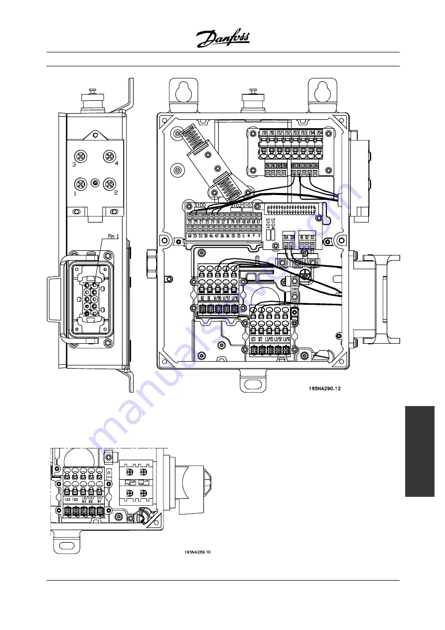
Page 81: ...s Installation FCD 300 T73 version with motor plug and sensor plugs Version is supplied from Danfoss with wiring as shown T63 version with service switch no motor plug MG 90 F2 22 VLT is a registered Danfoss trademark 81 ...
Page 82: ...al terminal block PE Ground connection See Technical data for correct dimensioning of cable cross section All types of three phase asynchronous standard motors can be connected to a variable frequency drive Normally small motors are star connected 230 400 V Y Large motors are delta connected 400 690 V Y The correct connection mode and voltage can be read from the motor nameplate NOTE In motors wit...
Page 83: ... the range The total current consumption of the motors is not to exceed the maximum rated output current IINV for the variable frequency drive Problems may arise at the start and at low rpm values if the motor sizes are widely different This is because the small motors relatively high ohmic resistance in the stator calls for a higher voltage at the start and at low rpm values In systems with motor...
Page 84: ... function 82 optional function Brake resistor terminals R R The connection cable to the brake resistor must be shielded armoured Connect the shield to the metal cabinet of the variable frequency drive and to the metal cabinet of the brake resistor by means of cable clamps Dimension the cross section of the brake cable to match the brake torque See chapter Dynamic Braking in the Design Guide MG 90 ...
Page 85: ...the chassis of the controlling unit use the instructions for the unit in question In connection with very long control cables and analog signals in rare cases depending on the installation 50 60 Hz ground loops may occur because of noise transmitted from AC line supply cables In this connection it may be necessary to break the shield and possibly insert a 100 nF capacitor between the shield and th...
Page 86: ...ications see the Operating Instructions MG 04 BX YY digital inputs terminals 18 19 29 33 Terminals 203 204 are used for sensor supply Terminal 203 common Terminal 204 24 V Terminals 201 202 can be used for a separate 24 V supply MG 90 F2 22 VLT is a registered Danfoss trademark 86 ...
Page 87: ...Operating Instructions MG 90 AX YY VLT 2800 FCD 300 DeviceNet Operating Instructions MG 90 BX YY or FCD 300 AS interface Operating Instructions MG 04 EX YY PC communication Connection to terminals P and N On non fieldbus and Profibus variants terminals 68 and 69 can be used as well Relay connection See parameter 323 Relay output for programming of relay output No 01 02 1 2 make normally open 01 03...
Page 88: ...ral Solutions Connection examples NOTE Avoid leading the cables over the plugs to the electronics Dont loosen screw fixing the spring for the PE connection MG 90 F2 22 VLT is a registered Danfoss trademark 88 ...
Page 89: ... is activated via terminal 29 Par 302 Digital input Pulse start 8 Par 303 Digital input Stop inverted 6 Par 304 Digital input Coasting stop inverted 2 Par 305 Digital input Jog 13 Speed up slow down Speed up slow down using terminals 29 33 Par 302 Digital input Start 7 Par 303 Digital input Freeze reference 14 Par 305 Digital input Speed up 16 Par 307 Digital input Slow down 17 Potentiometer refer...
Page 90: ...0 132 Hz 1 Par 203 Reference range Min ref Max ref 0 Par 204 Min reference 50 Hz Par 205 Max reference 50 Hz Par 302 Digital input Start 7 Par 304 Digital input Coasting stop inverted 2 Par 308 Analog input Reference 1 Par 309 Terminal 53 min scaling 0 Volt Par 310 Terminal 53 max scaling 10 Volt Preset references Switch between 8 preset references via two digital inputs and Setup 1 and Setup 2 Pa...
Page 91: ...100 00 This table shows what the output frequency is Preset ref msb Preset ref lsb Selection of Setup Output frequency Hz 0 0 0 2 5 0 1 0 5 1 0 0 10 1 1 0 17 5 0 0 1 20 0 1 1 25 1 0 1 35 1 1 1 50 Connection of mechanical brake Using terminal 122 123 Par 302 Digital input Start 7 Par 304 Digital input Coasting stop inverted 2 See also par 138 139 140 Mechanical brake with accelerator winding Par 30...
Page 92: ... mechanical brake NOTE Do not use the internal relay for DC brakes or brake voltages 250 V Counter stop via terminal 33 The start signal terminal 18 must be active i e logical 1 until the output frequency is equal to the reference The start signal terminal 18 logical 0 must then be removed before the counter value in parameter 344 has managed to stop the VLT frequency converter Par 307 Digital inp...
Page 93: ...control panel unless this function has been programmed as Locked 1 via parameter 018 Lock for data changes Control keys for parameter Setup The control keys are divided into functions in such a way that the keys between the display and the indicator lamps are used for parameter Setup including selection of the display s view mode during normal operation DISPLAY STATUS is used to select the display...
Page 94: ...an only be stopped by disconnecting the voltage to the motor or the variable frequency drive JOG changes the output frequency to a preset frequency while the key is held down Can be set to active or inactive via parameter 015 Local jog FWD REV changes the direction of rotation of the motor which is indicated by means of the arrow on the display Can be set to active or inactive via parameter 016 Lo...
Page 95: ...rating values can be displayed in lines 1 and 2 in Display mode Changes are made using the keys Switching between AUTO and HAND modes By activating the CHANGE DATA key in DISPLAY MODE the display will indicate the mode of the variable frequency drive Switch mode by using key HAND AUTO In HAND mode the reference can be changed by or keys Operating data Unit Resulting reference Resulting reference u...
Page 96: ...fly pressing the DISPLAY STATUS key MOTOR IS RUNNING 50 0 Hz 24 3 30 2 13 8A In this mode all data values for four operating data items with any pertaining units are shown see table In the example the following have been selected Frequency Reference Torque and Current as readout in the first and second line Display mode III This display mode is called up as long as the DISPLAY STATUS key is held d...
Page 97: ...cess to the most important parameters of the variable frequency drive After programming the variable frequency drive is in most cases ready for operation Scroll through the Quick menu using the keys and change the data values by pressing CHANGE DATA OK The Menu mode allows choosing and changing all parameters as required However some parameters will be shaded off depending on the choice in paramet...
Page 98: ... of the keys 50 0 Hz FREQUENCY 001 LANGUAGE ENGLISH The bottom display line will show the value that will be entered saved when acknowledgment is given OK Change of numeric data value If the selected parameter is represented by a numerical data value a digit is first chosen using the keys 50 0 HzSETUP 1 FREQUENCY 130 START FREQUENCY 09 0 HZ The selected digit can then be changed infinitely variabl...
Page 99: ... 3 the FWD REV key on the condition that is has been selected as active in parameter 016 Local reversing and that parameter 013 Local control is set at Local control and open loop 1 or Local control as parameter 100 3 Parameter 200 Output frequency range is set at Both directions 4 parameter 003 Local reference where the reference can be set using the and keys 5 an external control command that ca...
Page 100: ...in four individual parameter Setups Shifts between Setups can be made in this parameter via a digital input or via serial communication Description of choice Factory Setup 0 contains the factory set parameter values Setup 1 4 1 4 are four individual Setups which can be selected as required Multi Setup 5 is used where remote controlled shifts between the four Setups via a digital input or via seria...
Page 101: ... frequency converter to which the control panel is attached Select Download size independent par 3 if you only want to downloade the size independent parameters This is used when downloading to a variable frequency drive with a different rated power size than that from which the parameter setup originates NOTE Upload download can only be performed in stop mode Download can only be performed to a f...
Page 102: ... scaling selected in parameter 414 Minimum feedback FBLOW 415 Maximum feedback FBHIGH and 416 Process units Frequency Hz gives the output frequency of the variable frequency drive Output frequency x scaling equals the present output frequency fM multiplied by the factor set in parameter 008 Display scaling of output frequency Motor current A gives the phase current of the motor measured as an effe...
Page 103: ...uency in Hz connected to terminal 29 Pulse count gives the number of pulses that the unit has registered 010 Small display line 1 1 DISPLAY LINE 1 1 Value See par 009 Large display readout Reference 1 Function In this parameter the first of three data values can be selected that is to be displayed in the LCP control unit display line 1 position 1 This is a useful function e g when setting the PID ...
Page 104: ... to the reverse signal negative reference the reference will be set to 0 Shifting from Local operation to Remote operation in parameter 002 Local remote control while this parameter has been set to Remote operated control and open loop 1 The configuration selected in parameter 100 Configuration will be active The shift will be smooth Shifting from Remote control to Local control in parameter 002 L...
Page 105: ...aved reference LOCAL STOP 1 Forced stop set ref to 0 LOCAL STOP REF 0 2 Function Setting of the required operating mode when the electrical voltage is engaged This function can only be active if Local operation 1 has been selected in parameter 002 Local remote operation Description of choice Auto restart use saved ref 0 is selected if the variable frequency drive is to start using the local refere...
Page 106: ...e Order form Description of choice The Quick Menu is set up as follows 1 Select parameter 025 Quick Menu setup and press CHANGE DATA 2 Index 1 indicates the first parameter in Quick Menu You can scroll between the index numbers using the keys Select Index 1 3 Using you can scroll between the three figures Press the key once ad the last number in the parameter number can be selected using the keys ...
Page 107: ...Programming FCD 300 Description of choice Select the function to be visualized factory setting display text value for use in communication via serial communication port MG 90 F2 22 VLT is a registered Danfoss trademark 107 ...
Page 108: ...vant process unit or as a percentage A feedback signal must be added from the process and the process regulator must be set in parameter group 400 Special functions Process closed loop is not active if a DeviceNet card is mounted and Instance 20 70 or 21 71 is chosen in parameter 904 Instance types 101 Torque characteristic TORQUE CHARACT Value Constant torque CONSTANT TORQUE 1 Variable torque low...
Page 109: ... a value that corresponds to the nameplate data on the motor regardless of the variable frequency drive s AC line voltage 104 Motor frequency fM N MOTOR FREQUENCY Value 24 1000 Hz 50 Hz Function This is where to select the rated motor frequency fM N Description of choice Select a value that corresponds to the nameplate data on the motor 105 Motor current IM N MOTOR CURRENT Value 0 01 IMAX Depends ...
Page 110: ...th the optimized value Interrupting AMT AMT can be interrupted during the optimization procedure by giving a STOP signal When using the AMT function the following points should be observed For AMT to be able to define the motor parameters as well as possible the correct type plate data for the motor connected to the variable frequency drive must be keyed into parameters 102 to 106 Alarms will appe...
Page 111: ...s of the motor nameplate data 117 Resonance dampening RESONANCE DAMP Value 0 100 0 Function Reduces the output voltage when running at low load for avoiding resonance phenomena Description of choice If 0 is selected there will be no reduction If 100 is selected the voltage is reduced to 50 at no load 119 High start torque HIGH START TORQ Value 0 0 0 5 sec 0 0 sec Function To ensure a high start to...
Page 112: ... motor will always follow in the reference direction If the reference signal equals zero the output frequency will equal 0 Hz while the output voltage will correspond to the setting in parameter 131 Voltage at start If the reference signal is different from zero the output frequency will equal parameter 130 Start frequency and the output voltage will equal parameter 131 Voltage at start This funct...
Page 113: ...this parameter the DC brake time is set at which parameter 132 DC brake voltage is to be active Description of choice Set the required time 127 DC brake cut in frequency DC BRAKE CUT IN Value 0 0 OFF par 202 Output frequency high limit fMAX OFF Function In this parameter the DC brake cut in frequency is set at which the DC brake is to be activated in connection with a stop command Description of c...
Page 114: ... Trip if you want a trip when the motor is overloaded according to the calculations Select ETR warning 1 4 if you want a warning when the motor is overloaded according to the calculations You can also program the variable frequency drive to give a warning signal via one of the digital outputs Select ETR Trip 1 4 if you want a trip when the motor is overloaded according to the calculations NOTE Thi...
Page 115: ...0 100 00 V Depends on unit Function A higher start torque can be obtained by increasing the start voltage Small motors 1 0 HP normally require a high start voltage Description of choice The factory setting will be suitable for must applications the value may need to be increase gradually for high torque application Warning If the use of start voltage is exaggerated this may lead to over energizing...
Page 116: ...voltage 0 Function This parameter is used to keep the motor holding torque at start stop Description of choice This parameter can only be used if a selection has been made of DC hold in parameter 121 Start function or 122 Function at stop To be set as a percentage value of the max DC hold voltage which depends on the choice of motor 138 Brake cut out value BRAKE CUT OUT Value 0 5 132 0 1000 0 Hz 3...
Page 117: ... 1 0 is selected this corresponds to the AC brake being inactive NOTE If the value in par 144 is increased the motor current will simultaneously increase significantly when generator loads are applied The parameter should therefore only be changed if it is guaranteed during measurement that the motor current in all operating situations will never exceed the maximum permitted current in the motor P...
Page 118: ...t can be selected that corresponds to the minimum speed at which the motor is allowed to run If Both directions has been selected in parameter 200 Output frequency range the minimum frequency is of no significance Description of choice The value chosen can range from 0 0 Hz to the frequency set in parameter 202 Output frequency high limit fMAX 202 Output frequency high limit fMAX MAX OUTPUT FREQ V...
Page 119: ...ameters 009 012 Display readout if a readout is desired It is possible to have both references and external references simultaneously In parameter 214 Reference function a selection can be made to determine how preset references should be added to the external references There is also an independent local reference in parameter 003 Local reference in which the resulting reference is set using the ...
Page 120: ...he following table Par 100 Configuration Unit Open loop 0 Hz Speed reg closed loop 1 rpm Process reg closed loop 3 Par 416 Description of choice The minimum reference is preset if the motor has to run at a minimum speed regardless of whether the resulting reference is 0 205 Maximum reference RefMAX MAX REFERENCE Value Par 100 Config Open loop 0 Par 204 RefMIN 1000 000 Hz 50 000 Hz Par 100 Config C...
Page 121: ...n time is the deceleration time from the rated motor frequency fM N parameter 104 Motor frequency f M N to 0 Hz provided no overvoltage arises in the inverter because of generating operation of the motor Description of choice Set the required ramp down time 209 Ramp up time 2 RAMP UP TIME 2 Value 0 02 3600 00 sec 3 00 sec Function See description of parameter 207 Ramp up time 1 Description of choi...
Page 122: ...the digital inputs serial communication or via the LCP control panel on the condition that this is active in parameter 015 Local jog Description of choice Set the required frequency Reference function The example shows how the resulting reference is calculated when Preset references is used together with Sum and Relative in parameter 214 Reference function The formula for the calculation of the re...
Page 123: ...external references If Relative 1 is selected one of the added preset references parameters 215 218 Preset reference is summarized as a percentage of the sum of present external references If External preset 2 is selected it is possible via a digital input to shift between external references or preset references Preset references will be a percentage value of the reference range NOTE If Sum or Re...
Page 124: ...period the load is lower than IINV Please note that if the current limit is set at a lower value than IINV the acceleration torque will be reduced to the same extent Description of choice Set the required maximum output current ILIM 223 Warning Low current ILOW WARN CURRENT LO Value 0 0 par 224 Warning High current IHIGH 0 0 A Function If the output current falls below the preset limit ILOW a warn...
Page 125: ...al via terminal 46 and via the relay output Description of choice The output frequency s upper signal limit fHIGH must be programmed within the variable frequency drive s normal operating range See drawing at parameter 223 Warning Low current ILOW 227 Warning Low feedback FBLOW WARN FEEDB LOW Value 100 000 000 par 228 Warn FBHIGH 4000 000 Function If the feedback signal falls below the preset limi...
Page 126: ... can be defined on either side of these frequencies Description of choice The frequency set in this parameter will be centered around parameters 230 Frequency bypass 1 and 231 Frequency bypass 2 230 Frequency bypass 1 FREQ BYPASS 1 231 Frequency bypass 2 FREQ BYPASS 2 Value 0 1000 Hz 0 0 Hz Function Some systems call for some output frequencies to be avoided because of mechanical resonance problem...
Page 127: ... CATCH UP 19 19 19 19 19 Slow down SLOW DOWN 20 20 20 20 20 Ramp 2 RAMP 2 21 21 21 21 21 Preset ref LSB PRESET REF LSB 22 22 22 22 22 Preset ref MSB PRESET REF MSB 23 23 23 23 23 Preset reference on PRESET REFERENCE ON 24 24 24 24 24 Precise stop inverse PRECISE STOP INV 26 26 26 3 26 3 Precise start stop PRECISE START STOP 27 27 Pulse reference PULSE REFERENCE 28 1 28 Pulse feedback PULSE FEEDBAC...
Page 128: ...ected if a start stop command is required Logic 1 start logic 0 stop Latched start if a pulse is applied for min 14 ms the variable frequency drive will start the motor provided no stop command has been given The motor can be stopped by briefly activating Stop inverse Reverse is used for changing the direction of rotation of the motor shaft Logic 0 will not lead to reverse Logic 1 will lead to rev...
Page 129: ... 0 Preset ref 1 0 1 Preset ref 2 1 0 Preset ref 3 1 1 Preset ref 4 Preset reference on is used for shifting between remote controlled reference and preset reference It is assumed that External preset 2 has been selected in parameter 214 Reference function Logic 0 remote controlled references are active logic 1 one of the four preset references is active as can be seen from the table above Precise ...
Page 130: ...caling Description of choice No function 0 Is selected if the variable frequency drive is not to react to signals connected to the terminal Reference 1 If this function is selected the reference can be changed by means of an analog reference signal If reference signals are connected to more than one input these reference signals must be added up If a voltage feedback signal is connected select Fee...
Page 131: ...m reference value RefMAX Description of choice Set the required current value 317 Time out LIVE ZERO TIME O Value 1 99 sec 10 sec Function If the signal value of the reference or feedback signal connected to one of the input terminals 53 or 60 falls below 50 of the minimum scaling for a period longer than the time set the function selected in parameter 318 Function after time out will be activated...
Page 132: ...tput signal is obtained which is proportional to the feedback value in the interval Minimum feedback FBMIN Maximum feedback FBMAX parameter 414 415 0 fMAX 0 20 mA 4 20 mA An output signal is obtained which is proportional to the output frequency in the interval 0 fMAX parameter 202 Output frequency high limit fMAX 0 IINV 0 20 mA 4 20 mA An output signal is obtained which is proportional to the out...
Page 133: ...or warning Current limit the output current is higher than the value programmed in parameter 221 Current limit ILIM Alarm The output is activated by an alarm Output frequency higher than fLOW the output frequency is higher than the value set in parameter 225 Warning Low frequency fLOW Output frequency lower than fHIGH the output frequency is lower than the value set in parameter 226 Warning High f...
Page 134: ...ACK 26 Output frequency PULSE OUTPUTFREQ 27 Pulse current PULSE CURRENT 28 Pulse power PULSE POWER 29 Pulse temperature PULSE TEMP 30 Control word bit 12 CTRL W BIT 12 31 Function The digital output can be used for giving the present status or warning The digital output terminal 46 gives a 24 V DC signal when a given condition is fulfilled Description of choice External RefMIN RefMAX Par 0 342 An ...
Page 135: ...t terminal 33 In this way an internal stop signal will activate the normal ramp down time parameter 208 The counter function is activated starts timing at the flank of the start signal when it changes from stop to start Speed compensated stop To stop at precisely the same point regardless of the present speed a stop signal received is delayed internally when the present speed is lower than the max...
Page 136: ...it is assumed that the total delay from the Sensor PLC and other hardware corresponds to this setting NOTE Only active for speed compensated stop factory setting display text value for use in communication via serial communication port MG 90 F2 22 VLT is a registered Danfoss trademark 136 ...
Page 137: ...of times a restart is to be attempted The time between each attempt is set in parameter 406 Automatic restart time Description of choice If Manual reset 0 is selected reset is to be carried out via the STOP RESET key a digital input or serial communication If the variable frequency drive is to carry out an automatic reset and restart after a trip select data value 1 3 or 10 If Reset at power up 11...
Page 138: ...tput voltage which means that torque ripple on the motor shaft is avoided This can be a good feature e g on grinding machines On 1 means that an output voltage can be obtained which is greater than the AC line voltage up to 5 414 Minimum feedback FBMIN MIN FEEDBACK Value 100 000 000 par 415 FBMAX 0 000 Function Parameter 414 Minimum feedback FBMIN and 415 Maximum feedback FBMAX are used to scale t...
Page 139: ...ion is optimized for use in applications in which there is a need to maintain a particular motor speed The parameters that are specific for the speed regulator are parameter 417 to parameter 421 Process regulation The PID regulator maintains a constant process mode pressure temperature flow etc and adjusts the motor speed on the basis of the reference setpoint and feedback signal A transmitter pro...
Page 140: ...edback range If preset references are desired they are preset in parameters 215 to 218 Preset reference See description Reference Function and Handling of References If a current signal is used as the feedback signal it will only be possible to use voltage as an analog reference Use the overview below to determine which terminal is to be used and which parameters are to be programmed Reference typ...
Page 141: ...initialized at a frequency corresponding to the present output frequency This is a means of avoiding the integration of a variance between the reference and the process s actual mode that cannot be deregulated by means of a change of speed This function can be deselected in parameter 438 Process PID anti windup Starting conditions In some applications the optimal setting of the process regulator w...
Page 142: ...Decentral Solutions factory setting display text value for use in communication via serial communication port MG 90 F2 22 VLT is a registered Danfoss trademark 142 ...
Page 143: ...ate if an error has occurred 419 Speed PID differential time SPEED DIFF TIME Value 0 00 OFF 200 00 ms 20 00 ms Function The differentiator does not react to a constant error It only makes a contribution when the error changes The quicker the error changes the stronger the gain from the differentiator will be The contribution is proportional to the speed at which errors change Description of choice...
Page 144: ...ic on the basis of four definable voltages and three frequencies The voltage at 0 Hz is set in parameter 133 Start voltage Description of choice Set the output voltage U1 that is to match the first output frequency F1 parameter 424 F1 frequency 424 F1 frequency F1 FREQUENCY Value 0 0 par 426 F2 frequency Par 104 Motor frequency Function See parameter 423 U1 voltage Description of choice Set the ou...
Page 145: ...Description of choice If the variable frequency drive is to reduce the output frequency in case the feed back signal increases select Normal 0 If the variable frequency drive is to increase the output frequency in case the feedback signal increases select Inverse 1 438 Proces PID anti windup PROC ANTI WINDUP Value Not active DISABLE 0 Active ENABLE 1 Function It is possible to select whether the p...
Page 146: ...t error between the reference setpoint and the feedback signal The greater the error the quicker the integrator frequency contribution will increase The integral time is the time needed by the integrator to make the same change as the proportional gain Description of choice Quick regulation is obtained at a short integral time However this time may become too short which can make the process unsta...
Page 147: ...hoice Select Disable 0 if this function is not required Select OK same direction 1 if the motor shaft is only able to rotate in the same direction when cutting in OK same direction 1 should be selected if in parameter 200 Output frequency range a selection has been of Clockwise only Select OK both directions 2 if the motor is able to rotate in both directions when cutting in Select DC brake and st...
Page 148: ...e controller range is reduced the speed variations will be less during initial tuning 456 Brake Voltage Reduce BRAKE VOL REDUCE Value 0 200 V 0 Function The user sets the voltage by which the level for resistor braking is reduced It is only active when resistor in parameter 400 is selected Description of choice The greater the reduction value the faster the reaction to a generator overload Should ...
Page 149: ...sponding to a byte Each character is secured via a parity bit which is set at 1 when it reaches parity i e when there is an equal number of 1 s in the 8 data bits and the parity bit in total A character is completed by a stop bit thus consisting of 11 bits in all Telegram Structure Each telegram begins with a start character STX 02 Hex followed by a byte that denotes the length of the telegram LGE...
Page 150: ...used Bit 5 0 No Broadcast Bit 0 4 Adjustable frequency drive address 1 31 2 Address format 1 126 The byte for address range 1 126 has the following profile Bit 7 1 address format 1 126 active Bit 0 6 Adjustable frequency drive address 1 126 Bit 0 6 0 Broadcast The slave sends the address byte back unchanged in the response telegram to the master Example writing to adjustable frequency drive addres...
Page 151: ...nses AK Bits no 12 15 are used to transfer parameter commands from master to slave and the slave s processed responses back to the master Parameter commands master slave Bit no 15 14 13 12 Parameter command 0 0 0 0 No command 0 0 0 1 Read parameter value 0 0 1 0 Write parameter value in RAM word 0 0 1 1 Write parameter value in RAM double word 1 1 0 1 Write parameter value in RAM and EEprom double...
Page 152: ...eter value block PWE with a fault code value from 1 99 See Summary of Warnings and Alarms to identify the fault code Parameter value PWE The parameter value block consists of 2 words 4 bytes and the value depends on the defined command AK If the master prompts for a parameter value the PWE block does not contain a value If you wish the master to change a parameter value write the new value is writ...
Page 153: ... transformer Data types Description 3 Integer 16 4 Integer 32 5 Unsigned 8 6 Unsigned 16 7 Unsigned 32 9 Text string Unsigned means that there is no operational sign in the telegram Example Write a parameter value Parameter 202 Output frequency high limit fMAX to be changed to 100 Hz The value must be recalled after a electrical failure so it is written in EEPROM PKE E0CA Hex Write for parameter 2...
Page 154: ...sferred as a whole number a conversion factor must be used to transfer decimals Example Parameter 201 Output frequency low limit fMIN has a conversion factor of 0 1 If you wish to preset the minimum frequency to 10 Hz the value 100 must be transferred as a conversion factor of 0 1 means that the value transferred is multiplied by 0 1 The value 100 will thus be perceived as 10 0 Conversion table Co...
Page 155: ...d Note In parameter 502 Coasting stop a selection is made to define how Bit 03 gates with the corresponding function on a digital input Bit 04 Quick stop Bit 04 0 causes a stop in which the motor s speed is ramped down to stop via parameter 212 Quick stop ramp down time Bit 05 Freeze output frequency Bit 05 0 causes the present output frequency in Hz to freeze The frozen output frequency can now o...
Page 156: ...inputs Bit 15 Reverse Bit 15 0 causes no reverse Bit 15 1 causes reverse Note In the factory setting reverse is set to digital in parameter 506 Reverse Bit 15 only causes reverse when either Ser communication Logic or or Logic and is selected Status Word according to FC Profile The status word is used to inform the master e g a PC of the slave s variable frequency drive mode Slave Master Bit Bit 0...
Page 157: ... to control the variable frequency drive via serial communication Bit 10 Outside frequency range Bit 10 0 if the output frequency has reached the value in parameter 201 Output frequency low limit or parameter 202 Output frequency high limit Bit 10 1 means that the output frequency is within the defined limits Bit 11 Running not running Bit 11 0 means that the motor is not running Bit 11 1 means th...
Page 158: ...according to FC protocol Bit 08 Jog 1 Bit 08 1 means that the output frequency is determined by parameter 09 Bus jog 1 Bit 09 Jog 2 Bit 09 1 means that the output frequency is determined by parameter 510 Bus jog 2 Bit 10 Data not valid Data valid See description under Control word according to FC protocol Bit 11 Slow down Used to reduce the speed reference by the value in parameter 219 Catch up sl...
Page 159: ... the control word 1 Bit 05 1 means that Bit 02 in the control word 0 Bit 06 Start enable start disable Bit 06 1 after reset of a trip after activation of OFF2 or OFF3 and after connection of AC line voltage Start disable is reset by setting Bit 00 in the control word to 0 and Bit 01 02 and 10 are set to 1 Bit 07 Warning See description under Status word according to FC protocol Bit 08 Speed See de...
Page 160: ...t 1101 1111 1111 1111 1111 1 2 complement 1110 0000 0000 0000 0000 Control word 047F Hex Start command Reference E000 Hex 50 reference Present output frequency The value of the variable frequency drive s present output frequency is transferred as a 16 bit word The value is transferred as whole numbers 0 32767 200 16384 4000 Hex corresponds to 100 Output frequency has the following format 0 16384 4...
Page 161: ...e serial port but must be preset via the operating unit 502 Coasting Stop COASTING SELECT Value Digital input DIGITAL INPUT 0 Serial port SERIAL PORT 1 Logic and LOGIC AND 2 Logic or LOGIC OR 3 Function Parameters 502 508 allow a choice between controlling the variable frequency drive via the digital inputs and or via the serial port If Serial port 1 is selected the relevant command can only be ac...
Page 162: ...3 Dig input Ser port Function 0 0 Coasting 0 1 Coasting 1 0 Coasting 1 1 Motor running factory setting display text value for use in communication via serial communication port MG 90 F2 22 VLT is a registered Danfoss trademark 162 ...
Page 163: ...0 0 Quick stop 0 1 Quick stop 1 0 Quick stop 1 1 Motor running 504 DC brake DC BRAKE SELECT Value Digital input DIGITAL INPUT 0 Serial port SERIAL PORT 1 Logic and LOGIC AND 2 Logic or LOGIC OR 3 Function See function description for parameter 502 Coasting stop Description of choice The table below shows when the motor is running and the DC braking when each of the following is selected Digital in...
Page 164: ...SE SELECT Value Digital input DIGITAL INPUT 0 Serial port SERIAL PORT 1 Logic and LOGIC AND 2 Logic or LOGIC OR 3 Function See function description for parameter 502 Coasting stop Description of choice The table below shows when the motor is running clockwise and counter clockwise when each of the following is selected Digital input 0 Serial port 1 Logic and 2 or Logic or 3 Digital input 0 Dig inp...
Page 165: ... Setup 4 Serial communication 1 Setup msb Setup lsb Function 0 0 Setup 1 0 1 Setup 2 1 0 Setup 3 1 1 Setup 4 Logic and 2 Bus Setup msb Bus Setup lsb Dig Setup msb Dig Setup lsb Setup no 0 0 0 0 1 0 0 0 1 1 0 0 1 0 1 0 0 1 1 1 0 1 0 0 1 0 1 0 1 2 0 1 1 0 1 0 1 1 1 2 1 0 0 0 1 1 0 0 1 1 1 0 1 0 3 1 0 1 1 3 1 1 0 0 1 1 1 0 1 2 1 1 1 0 3 1 1 1 1 4 Logic or 3 Bus Setup msb Bus Setup lsb Dig Setup msb D...
Page 166: ...s of control word profiles 513 Bus time interval BUS TIMEOUT TIME Value 1 99 sec 1 sec Function In this parameter it is possible to preset the maximum time expected to elapse between receipt of two consecutive telegrams If this time is exceeded the serial communication is assumed to have stopped and the desired reaction is preset in parameter 514 Bus time interval function Description of choice Pr...
Page 167: ... Hex 541 Extended status word EXT STATUS WORD Hex 544 Pulse count PULSE COUNT 545 Term 29 pulse input PULSE INPUT 29 Hz Function These parameters can be read out via the serial communication port and the LCP display See also parameters 009 012 Display readout NOTE Parameters 515 541 can only be read out via the serial communication port Description of choice Resulting reference parameter 515 Gives...
Page 168: ...ce parameter 533 Gives the sum of external references as a percentage sum of analog pulse serial communication in the range from Minimum reference RefMIN to Maximum reference RefMAX Status word parameter 534 Gives the present status word for the variable frequency drive in Hex See Serial communication for the VLT 2800 Inverter temperature parameter 537 Gives the present inverter temperature on the...
Page 169: ...number 10 contains the oldest data value Description of choice Read out as one value 617 Fault log Value F LOG VALUE Value Index 1 10 Value 0 9999 Function In this parameter it is possible to see at which value a trip occurred The unit of the value depends on which alarm is active in parameter 615 Fault log Fault code Description of choice Read out as one value 618 Reset of kWh counter RESET KWH C...
Page 170: ...nect the AC line voltage and wait until the light in the display has disappeared 3 Mount according to drawing and description 4 Connect the AC line voltage 5 The variable frequency drive automatically undertakes a test of the control card If the LEDs are flashing a code 4 LEDs alternatively the control card test has failed see the section Internal faults for further details Change the control card...
Page 171: ...LCP appears here Example ID 1 42 2 kB Parameter 626 Nameplate Database ID number The ID number of the software s database appears here Example ID 1 14 Parameter 627 Nameplate Power section version The ID number of the unit s power section appears here Example ID 1 15 Parameter 628 Nameplate Application option type Here you can see which types of application options are installed in the variable fr...
Page 172: ...VER 3 Function This parameter enables a configuration of a Profibus Control Card The default value depends on the produced unit also being the maximum obtainable value This means that a control card only can be downgraded to a lower performance version factory setting display text value for use in communication via serial communication port MG 90 F2 22 VLT is a registered Danfoss trademark 172 ...
Page 173: ...C braking function makes it possible to reduce the brake power in the motor instead of in a brake resistor The function is intended for applications where the required braking torque is less than 50 of rated torque AC braking is selected in par 400 Brake function NOTE The AC brake cannot be used if the required braking torque is more than 50 of rated braking torque In such instances a brake resist...
Page 174: ...g power that is applied to the brake resistor when the motor applies the brakes PPEAK is smaller than PPEAK MEC as the power is reduced by the efficiency of the motor and the variable frequency drive The peak effect is calculated as follows If you select Danfoss recommended braking resistor RREC you are certain that the braking resistance can generate a braking torque of 160 on the motor shaft Cal...
Page 175: ...c to DC braking there will be a short period 2 6 milliseconds with very low braking torque How to calculate optimum DC brake cut in frequency Slip S Synchronous speed 1 min f frequency p no of pole pairs nn speed of the rotor DC brake cut in frequency Hz Brake cable Max length ft 30 ft 10 m In the great majority of cases the variable frequency drive is used by professionals of the trade as a compl...
Page 176: ...a nonflammable material For protection of the installation a thermal relay is fitted that cuts out the variable frequency drive if the brake current is too high Danfoss 40 brake resistors contain a KLIXON switch Flat pack resistors are self protecting The brake current setting on the thermal relay is calculated as follows RBR is the brake resistor value at any given time The drawing shows an insta...
Page 177: ...esistor For occasional braking or braking with low duty cycle internally mountable brake resistors are available See Accessories for FCD 300 Mechanical dimensions of flatpack brake resistors 100 W 200 W MG 90 F2 22 VLT is a registered Danfoss trademark 177 ...
Page 178: ...Decentral Solutions Dimensions of mounting brackets MG 90 F2 22 VLT is a registered Danfoss trademark 178 ...
Page 179: ...ot be used for supply for the digital inputs on these terminals Serial communication connected to terminals 67 70 is galvonically isolated from the control terminals although this is only a functional isolation The relay contacts on terminals 1 3 are isolated from the other control circuits with increased isolation i e PELV is observed for these even though there is AC input potential in the relay...
Page 180: ...round fault The IGBT module cuts out within 100 µs in case of a ground fault on one of the motor terminals U V W 96 97 98 although depending on impedance and motor frequency Output connection Motor terminals U V W 96 97 98 for the motor can be connected disconnected as often as required There is no way that the variable frequency drive can be destroyed by connecting disconnecting the motor termina...
Page 181: ...e circuit UPEAK and dU dt influence the lifetime of the motor especially motors without phase insulation paper in the coils If the motor cable is short a few feet the overshoot UPEAK is low while the dU dt is high If the motor cable length is increased UPEAK is increased while dU dt decreases Switching on the input The waiting time between switching the electrical voltage on terminals 91 92 and 93...
Page 182: ... TAMB versus altitude at 100 output current Derating for running at low speed When a motor is connected to a variable frequency drive it is necessary to ensure adequate cooling of the motor At low rpm values the motor fan is not able to supply an adequate volume of cooling air This problem occurs when the load torque is constant e g with a conveyor belt across the full regulating range The reduced...
Page 183: ... Efficiency of the motor ηMOTOR The efficiency of a motor connected to the variable frequency drive depends on the sine shape of the current In general the efficiency is just as good as in AC line operation The efficiency of the motor depends on the motor type In the range of 75 100 of the rated torque the efficiency of the motor is practically constant both when it is controlled by the variable f...
Page 184: ... correction batteries Power factor The power factor Pf is the relation between I1 and IRMS The power factor for 3 phase supply The power factor indicates the extent to which the variable frequency drive imposes a load on the electrical supply The lower the power factor the higher the IRMS for the same HP kW performance In addition a high power factor indicates that the different harmonic currents ...
Page 185: ...cording to following product standards on a system consisting of a FCD 300 a shielded armoured control cable with control box and potentiometer shielded armoured motor cable shielded armoured brake cable and LCP with cable FCD 300 Product standard environment Test results Complies EN 61000 6 2 Industry See Basic standards test results Complies EN 61800 3 Second environment See Basic standards test...
Page 186: ...ed 61000 4 3 AC lines distortion VDE 0160 RF in voltage 2 61000 4 6 Acceptance criterion B B B A A Port connection CM DM CM Field DM CM Line OK OK OK Motor OK Control lines OK OK1 OK Relay OK OK OK Profibus OK OK1 OK Signal interface 10 ft 3 m OK Enclosure OK OK Standard bus OK OK1 OK Basic speci fications Line 2 kV DCN 1 kV 2 kV 10 Vrms Motor 10 Vrms Control lines 2 kV CCC 4 kV 2 1 10 Vrms Relay ...
Page 187: ... the table Further detailed status information can be obtained using a local control panel LCP2 see photo This can be connected on the outside without opening the enclosure if the LCP2 plug shown on the drawing is installed The LCP2 is an easy to navigate user friendly interface used to access and adjust all parameters It displays parameters in six different languages The FCD 300 holds a log with ...
Page 188: ...ocal stop Fast flashing Interface working but no communication with master See field bus manual for specific info Not relevant for non field bus device 2 Bus Green On If bus op tion is present else Off Off Status for the field bus not OK Not relevant for non field bus device Off No alarm is present 3 Alarm Red Off Flashing Flashing while trip trip lock is present Off No warning is present 4 Warn i...
Page 189: ...l blink After a reset the variable frequency drive will be ready to start operation again No Description Warning Alarm Trip locked 2 Live zero error LIVE ZERO ERROR X X X 4 Electrical phase loss MAINS PHASE LOSS X X X 5 Voltage warning high DC LINK VOLTAGE HIGH X 6 Voltage warning low DC LINK VOLTAGE LOW X 7 Overvoltage DC LINK OVERVOLT X X X 8 Undervoltage DC LINK UNDERVOLT X X X 9 Inverter overl...
Page 190: ...t Note Voltage warning high warning 5 will thus also be able to generate an alarm 7 WARNING ALARM 8 Undervoltage If the intermediate circuit voltage UDC is lower than the inverter s Undervoltage limit the inverter will be switched off until the UDC once more goes above the undervoltage limit If the UDC remains under the undervoltage limit the inverter will trip after a set time The time depends on...
Page 191: ...range in extended status word will be active but there will not be a warning in the display WARNING ALARM 34 HPFB communication fault Communication fault only occurs in Profibus versions ALARM 35 Inrush fault This alarm occurs when the variable frequency drive has been connected to the electrical supply too many times within 1 minute WARNING ALARM 36 Overtemperature If the internal temperature ris...
Page 192: ...at least one of the motor phases is too low The motor in use is probably too small for AMT calculations to be performed ALARM 51 AMT Fault re nameplate data There is inconsistency between the registered motor data Check the motor data for the relevant setup ALARM 54 AMT incorrect motor AMT cannot be performed on the motor being used ALARM 55 AMT timeout Calculations are taking too long possibly du...
Page 193: ... as a spare part The following four parts can replace all FCD 303 330 with and without Profibus For servicing DeviceNet and AS interface units an additional control card is required to upgrade the electronic spare part FCD 303 178B1484 FCD 307 178B1485 FCD 315 178B1486 FCD 330 178B2301 The parts can be downsized one size simply by selecting the correct motor size and the Profibus functionality can...
Page 194: ... torque 160 in 1 min Starting torque parameter 101 Torque characteristics Variable torque 160 in 1 min Starting torque parameter 119 High starting torque 180 for 0 5 sec Overload torque parameter 101 Torque characteristic Continuous torque 160 Overload torque parameter 101 Torque characteristic Variable torque 160 Percentage relates to adjustable frequency drive s nominal current Control card digi...
Page 195: ... logic 0 5 V DC Voltage level logic 1 10 V DC Maximum voltage on input 28 V DC Input resistance Ri approx 2 k Scan interval 13 3 msec Resolution 10 bit Accuracy 100 Hz 1 kHz terminal 33 Max error 0 5 of full scale Accuracy 1 kHz 67 6 kHz terminal 33 Max error 0 1 of full scale The pulse input is galvonically isolated from the supply voltage PELV and other high voltage terminals See section entitle...
Page 196: ...the supply voltage PELV and other high voltage terminals See section entitled Galvanic Isolation Control card RS 485 serial communication Terminal number 68 TX RX 69 TX RX Terminal number 67 5 V Terminal number 70 Common for terminals 67 68 and 69 Full galvanic isolation See section entitled Galvonic Isolation Relay outputs Number of programmable relay outputs 1 Terminal number control card 1 3 br...
Page 197: ... stop terminals 18 19 0 5 msec System response time terminals 18 19 27 29 33 26 6 msec Speed control range open loop 1 15 of synchronous speed Speed control range closed loop 1 120 of synchronous speed Speed accuracy open loop 1 1 HP 150 3600 rpm Max error of 23 rpm Speed accuracy open loop 0 75 HP 90 3600 rpm Max error of 23 rpm Speed accuracy closed loop 30 3600 rpm Max error of 7 5 rpm All cont...
Page 198: ...ower module is below 160 F 70 C The frequency converter is protected against short circuits on motor terminals U V W If an electrical phase is missing the variable frequency drive will cut out Monitoring of the intermediate circuit voltage ensures that the variable frequency drive cuts out if the intermediate circuit voltage is too low or too high The variable frequency drive is protected against ...
Page 199: ...pre fuses IEC UL 2 A 25 25 25 25 25 25 25 25 25 25 25 25 25 25 25 25 Efficiency3 96 Power loss at max load W 22 29 40 59 80 117 160 190 Weight kg 5 8 5 8 5 8 5 8 5 8 9 5 9 5 9 5 At electrical voltage min 3 x 460 480 V tamb max 95 F 35 C 1 American Wire Gauge Max cable cross section is the largest cable cross section that can be attached to the terminals Always observe national and local regulation...
Page 200: ... unit Operating instructions MG 04 BX YY Various literature for FCD 300 Data sheet MD 04 AX YY Design Guide Decentral Solutions MG 90 FX YY Communication with FCD 300 Profibus DP V1 Operating Instructions MG 90 AX YY DeviceNet Operating Instructions MG 90 BX YY AS i Operating Instructions MG 04 EX YY X version number YY language version MG 90 F2 22 VLT is a registered Danfoss trademark 200 ...
Page 201: ... active Yes 0 5 016 Local reversing Not active Yes 0 5 017 Local reset of trip Active Yes 0 5 018 Data change lock Not locked Yes 0 5 019 Operating status at power up Forced stop use saved ref Yes 0 5 020 Lock for Hand mode Active No 0 5 024 User defined Quick Menu Not active No 0 5 025 Quick Menu Setup 000 No 0 6 026 LED Status Overload Yes 0 5 4 Setup Yes means that the parameter can be programm...
Page 202: ...s Data type Data type shows the type and length of the telegram Data type Description 3 Integer 16 4 Integer 32 5 Unsigned 8 6 Unsigned 16 7 Unsigned 32 9 Text string MG 90 F2 22 VLT is a registered Danfoss trademark 202 ...
Page 203: ...ec Yes 1 5 120 Start delay 0 0 sec Yes 1 5 121 Start function Coast in start del Yes 0 5 122 Function at stop Coast Yes 0 5 123 Min freq for activation of par 122 0 1 Hz Yes 1 5 126 DC braking time 10 sec Yes 1 6 127 DC brake engaging frequency OFF Yes 1 6 128 Thermal motor protection No protection Yes 0 5 130 Start frequency 0 0 Hz Yes 1 5 131 Voltage at start 0 0 V Yes 1 6 132 DC brake voltage 0...
Page 204: ...mp time 3 00 sec Yes 2 7 212 Quick stop ramp down time 3 00 sec Yes 2 7 213 Jog frequency 10 0 Hz Yes 1 6 214 Reference function Sum Yes 0 5 215 Preset reference 1 0 00 Yes 2 3 216 Preset reference 2 0 00 Yes 2 3 217 Preset reference 3 0 00 Yes 2 3 218 Preset reference 4 0 00 Yes 2 3 219 Catch up slow down reference 0 00 Yes 2 6 221 Current limit 160 Yes 1 6 223 Warn Low current 0 0 A Yes 1 6 224 ...
Page 205: ...3 max scaling 10 0 V Yes 1 6 314 Term 60 analog input current No function Yes 0 5 315 Term 60 min scaling 0 0 mA Yes 4 6 316 Term 60 max scaling 20 0 mA Yes 4 6 317 Time out 10 sec Yes 1 5 318 Function after timeout No function Yes 0 5 319 Term 42 analog output 0 IMAX 0 20 mA Yes 0 5 323 Relay output No function Yes 0 5 327 Pulse Max 33 5000 Hz Yes 0 7 328 Pulse Max 29 5000 Hz Yes 0 7 341 Term 46 ...
Page 206: ...ion limit 5 0 Yes 1 6 421 Speed PID lowpass filter 20 ms Yes 3 6 423 U1 voltage par 103 Yes 1 6 424 F1 frequency Par 104 Yes 1 6 425 U2 voltage par 103 Yes 1 6 426 F2 frequency par 104 Yes 1 6 427 U3 voltage par 103 Yes 1 6 428 F3 frequency par 104 Yes 1 6 437 Proc PID no inv Normal Yes 0 5 438 Proc PID anti wind Active Yes 0 5 439 Proc PID start frequency Par 201 Yes 1 6 440 Proc PID start propor...
Page 207: ...y No 1 3 519 Data readout Frequency x scaling No 1 3 520 Data readout Motor current No 2 7 521 Data readout Torque No 1 3 522 Data readout Power kW No 1 7 523 Data readout Power HP No 2 7 524 Data readout Motor voltage V No 1 6 525 Data readout DC Link voltage No 0 6 526 Data readout Motor thermal load No 0 5 527 Data readout Inverter thermal load No 0 5 528 Data readout Digital input No 0 5 529 D...
Page 208: ...ode Normal operation No 0 5 621 Nameplate Unit type No 0 9 624 Nameplate Software version No 0 9 625 Nameplate LCP identification no No 0 9 626 Nameplate Database identification no No 2 9 627 Nameplate Power parts version No 0 9 628 Nameplate Application option type No 0 9 630 Nameplate Communication option type No 0 9 632 Nameplate BMC software identification No 0 9 634 Nameplate Unit identificat...
Page 209: ...ing 45 Control Word 154 157 Counter stop via terminal 33 92 Counter value 135 Current limit 124 Current Ratings AC53a ratings 56 Current minimum value 116 D Data Character byte 151 Data readout 166 DC brake time 113 DC brake voltage 115 DC Braking 113 DC hold voltage 116 Derating 182 Derating curve for altitude 44 Derating curve for temperature 44 Derating for running at low speed 182 Description ...
Page 210: ...eference 99 Lock for data changes 105 Lowpass filter 140 M Manual initialization 98 MCT 10 29 Mechanical brake 84 92 Mechanical dimensions of flatpack brake resistors 177 Mechanical dimensions FCD motor mounting 69 Mechanical dimensions stand alone mounting 69 Mechanical Installation 70 Motor cable 182 197 Motor cables 83 Motor connection 82 Motor current 109 Motor frequency 109 Motor mounting 43 ...
Page 211: ... Resonance dampening 111 RFI switches 78 S Slow down 124 Safety regulations 42 Sensor supply T63 T73 196 Sensors 86 Serial communication 47 Service switch 58 Setup copying 100 Setup shift 100 Setups 99 Shielded armoured cables 73 Short circuit 180 Slip compensation 116 Special motor mode 108 Special variants 58 Speed comp delay 135 Speed control closed loop 108 Speed control open loop 108 Speed PI...
Page 212: ...lection table 51 U U f ratio 116 UL Standard 183 V Variable torque 108 Various literature 200 Ventilation 44 Version no 42 W Wall mounting 43 Warning functions 124 Warning words extended status words and alarm words 192 Warnings alarm messages 189 2 24 V DC 196 24 V DC supply 87 24 V external supply 22 4 4 20 mA reference 90 4 Setup 201 MG 90 F2 22 VLT is a registered Danfoss trademark 212 ...