background image

General

Description

Comment

Configuration

Sourcing or sinking.

Type (Linear vs. PWM)

PWM

Operating modes

Programmable: closed loop current or open loop voltage (duty cycle).

Dual coil PCPs

Compensated for induced currents in a non-driven coil (closed loop mode).

Short circuit to ground

Output fully protected against damage and fault detected.

Mode selection (current or voltage) and full scale current
ranges

Programmable.

Do not connect a digital output to (back drive) without a series diode.

PLUS+1

®

 PWM output circuits are not designed to be used as inputs. Output current feedback readings

should be used for fault checking only.

W

Warning

Unintended movement of the machine or mechanism may cause injury to the technician or bystanders.

The module will be powered up if battery voltage is applied to the module's output pin. To protect

against unintended movement, secure the machine.

C

Caution

Warranty will be voided if module is damaged by significant current driven back through an output pin.
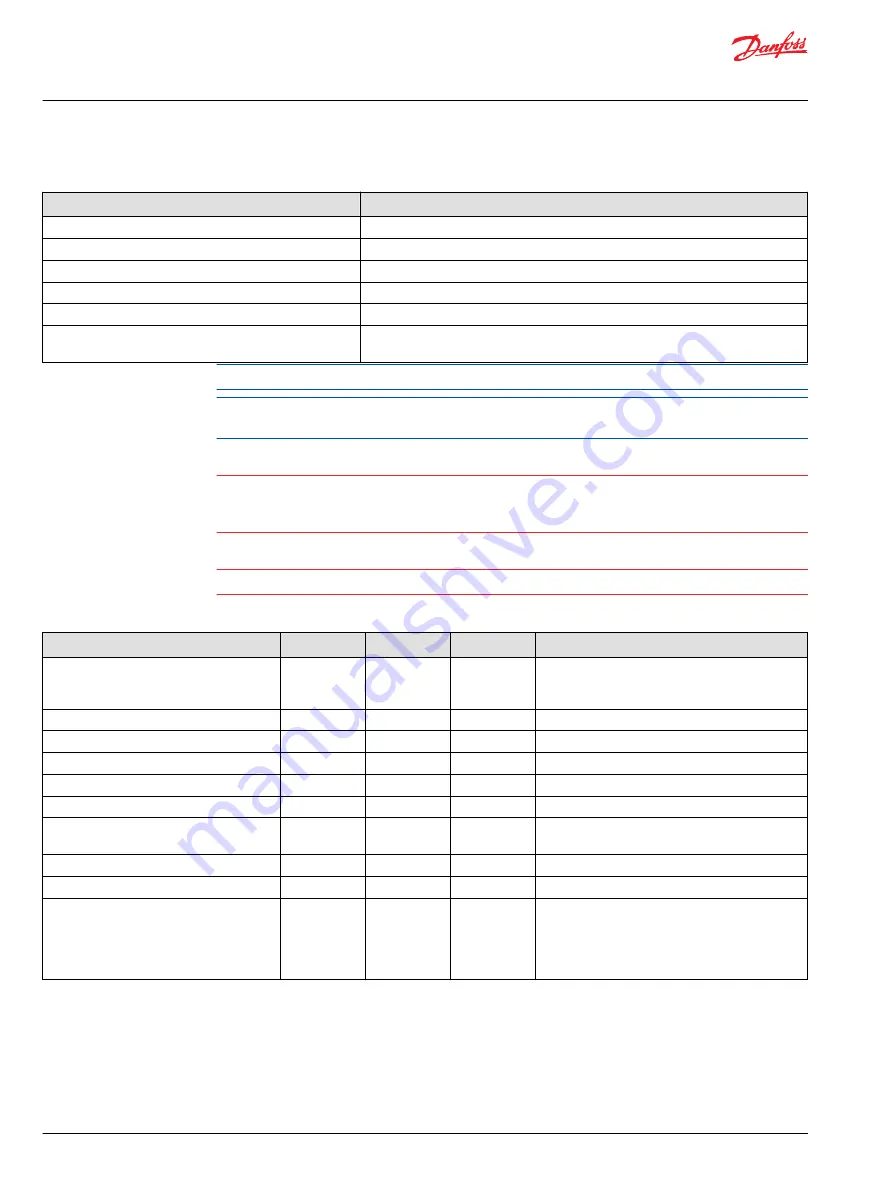
Specifications

Description

Units

Minimum

Maximum

Comment

Full scale proportional 
current output

mA

10

3000

The current may accidently be exceeded in open
loop mode. If the current exceeds the trip point, the
output will be latched off.

Output voltage, 100% duty cycle

Vdc

0

Vbatt-1

Output resolution of 3 A

mA

0.25

Repeatability of full range

% of full scale

0.5

Absolute accuracy of full range

% of full scale

0.3

Output settling time

ms

100

Depends on load characteristics.

PWM frequency

Hz

33

4000 and
20,000

Dither frequency

Hz

40

250

Increased in steps, see module API.

Dither amplitude

A

0

0.5

Increased in steps, see module API.

Over-current trip point

A

5

7.3

There is over-current protection built into each
output driver. If the instantaneous current exceeds
the trip point, the driver is latched off. GUIDE
application software can reset the latch and attempt
to drive current again.

For each PWM output there are two switches in series for sourcing current/voltage (the high-side of the
half bridge has two switches). One switch is controlled and monitored by the secondary controller, and
the other is controlled and monitored by the primary processor. The secondary controller can monitor
the condition of the redundant switch under its control with a digital voltage feedback signal. Each
sourcing PWM output can be disconnected from its supply voltage at any time by the secondary
controller with this redundant switch. When the redundant switch is disabled it must remain disabled by
the kernel for 250 ms before the secondary controller's application is allowed to re-enable the redundant
switch. When the switch controlled by the secondary controller is enabled then the PWM outputs are

Technical Information

PLUS+1 SC0XX-1XX Controller Family

Outputs


14 | 

©

 Danfoss | June 2016

L1415500 | BC00000235en-US0201

Summary of Contents for PLUS+1 SC0XX-1 Series

Page 1: ...Technical Information PLUS 1 SC Controllers SC0XX 1XX Controller Family powersolutions danfoss com...

Page 2: ...log Resistance 4 20 mA Current DIN AIN ResIN CrntIN Specifications 0201 March 2015 Various text update and added tables for control of outputs BA December 2014 First edition AA Technical Information P...

Page 3: ...cations CAN Controller Area Network 16 CAN system design 16 Specifications for terminating resistor 16 Notes on CAN Bus installation 16 Expansion module CAN Bus loading 16 Internal processor to proces...

Page 4: ...riable settings API specifications are the definitive source of information regarding pin characteristics PLUS 1 GUIDE User Manual This user operation manual OM details information regarding the PLUS...

Page 5: ...e OS that is embedded in their respective SC0XX 1XX HWD files The SC0XX 0XX Controller Family is designed for meeting the needs of SIL 2 applications where the OEM certifies at the machine level The S...

Page 6: ...hat are used for development testing configuration management quality control etc comply with the 250 requirements of the IEC 61508 international standard Use of certified devices makes it much easier...

Page 7: ...nput or output types are user configurable using PLUS 1 GUIDE software Refer to product data sheets for the input output I O content of individual modules Technical Information PLUS 1 SC0XX 1XX Contro...

Page 8: ...atching reading saturates to the high limit Response to input open Pin configuration dependent No pull up no pull down floating Pull up to 5 Vdc 5 Vdc Pull down 0 Vdc Pull up pull down 2 5 Vdc Voltage...

Page 9: ...ll down pull up is standard with pull up or pull down programmable failure modes are detectable Maximum frequency The controller may re boot under some high frequency load conditions above 10 kHz Spec...

Page 10: ...uired for frequency input to read low Rising voltage threshold low range Vdc 0 11 0 30 Voltage required for frequency input to read high Falling voltage threshold low range Vdc 0 04 0 22 Voltage requi...

Page 11: ...case error high range Vdc 1 16 Over the full temperature range 40 C to 85 C 40 F to 185 F Maximum discernable voltage middle range Vdc 5 13 5 38 Minimum discernable voltage middle range mV 0 20 Precis...

Page 12: ...the module s output pin To protect against unintended movement secure the machine C Caution Warranty will be voided if module is damaged by significant current driven back through an output pin Digit...

Page 13: ...to the off state 3 The secondary application can then re enable the output BIT 8 Hardware supply power out of range 1 The primary application must command ALL outputs to the off state 2 The supply vo...

Page 14: ...A 0 25 Repeatability of full range of full scale 0 5 Absolute accuracy of full range of full scale 0 3 Output settling time ms 100 Depends on load characteristics PWM frequency Hz 33 4000 and 20 000 D...

Page 15: ...put BIT 8 Hardware supply power out of range 1 The primary application must command ALL outputs to the off state 2 The supply voltage must return to its valid range 3 The kernel then clears status bit...

Page 16: ...of the CAN_H and CAN_L conductors This termination resistance should be connected between the CAN_H and CAN_L conductors Specifications Description Units Minimum Maximum Nominal Comment Resistance 11...

Page 17: ...nostics The hardware and low level software provide a basic framework for communication on each channel however the specific data structure is not predefined because the data to be transferred is appl...

Page 18: ...ure gives OEM designers the ability to implement automotive like features in their machine control system design If the lower power mode feature is not implemented this controller has the same operati...

Page 19: ...aximum Comment Output short circuit voltage Vdc 36 Sensor output voltage Vdc 3 12 Output current mA 0 500 The maximum power must be limited to 2 5 Watts for Vout greater than 5 Vdc Output Load Capacit...

Page 20: ...85 185 Storage temperature C F 40 40 85 185 Allowable module supply voltage Vdc 7 36 Module sensor supply voltage Vdc 3 12 Sensor voltage drops below the minimum value if module supply voltage 7 Vdc...

Page 21: ...ibility for earth moving machinery Electrostatic discharge EN 60 1 000 4 2 Auto electrical transients ISO 7637 2 ISO 7637 3 Short circuit protection Danfoss test Inputs and outputs survive continuous...

Page 22: ...05 0413 204 2005 Danfoss mating connector part information Description 24 pin module 50 pin module Mating connector bag assembly 20 to 24 AWG 10100945 10100946 Mating connector bag assembly 16 to 20 A...

Page 23: ...on modules be connected to a common ground A dedicated ground wire of appropriate size connected to the machine battery is recommended Hot plugging Machine power should be off when connecting PLUS 1 m...

Page 24: ...US 1 USB CAN Gateway Communication software uploads and downloads and service and diagnostic tool interaction between PLUS 1 modules and a personal computer PC is accomplished using the vehicle s PLUS...

Page 25: ...Technical Information PLUS 1 SC0XX 1XX Controller Family Danfoss June 2016 L1415500 BC00000235en US0201 25...

Page 26: ...Technical Information PLUS 1 SC0XX 1XX Controller Family 26 Danfoss June 2016 L1415500 BC00000235en US0201...

Page 27: ...Technical Information PLUS 1 SC0XX 1XX Controller Family Danfoss June 2016 L1415500 BC00000235en US0201 27...

Page 28: ...DK 6430 Nordborg Denmark Phone 45 7488 2222 Danfoss Power Solutions US Company 2800 East 13th Street Ames IA 50010 USA Phone 1 515 239 6000 Danfoss Power Solutions Trading Shanghai Co Ltd Building 22...

Reviews: