background image


Application

Submodules

Cyclic input data

Cyclic output data

20 signals (80 bytes)

Motion

4 signals (16 bytes)
8 signals (32 bytes)
12 signals (48 bytes)
16 signals (64 bytes)
20 signals (80 bytes)

4 signals (16 bytes)
8 signals (32 bytes)
12 signals (48 bytes)
16 signals (64 bytes)
20 signals (80 bytes)

Each of the selections in a signal module can comprise the following data types:

Boolean
Unsigned 8/16/32
Signed 8/16/32
Float 32

The buffer size adapts to the data type of the selected signals. If a Boolean type is mapped, only bit 0 is used in the chosen signal
address, and the remaining 7 bits are not used.
The actual interpretation of the value that is read or written depends on the data type and representation. For example, motor
current is a real-type 32-bit value that is represented as float, and publishing the motor current as an actual value does not need any
scaling and factoring.

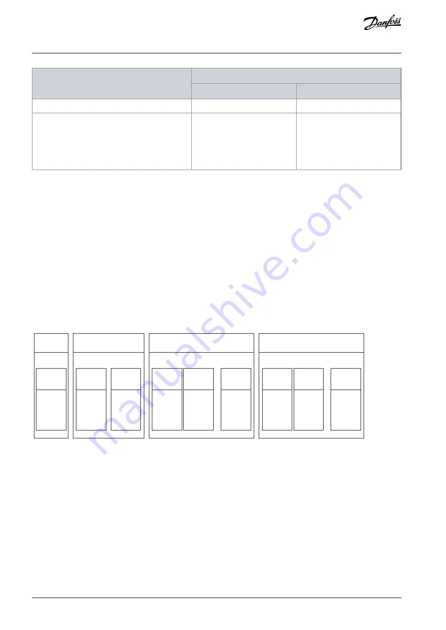
2.5.1 Functional Extension Options

Each functional extension option is defined by its own PROFINET device model with a module and submodule(s).
Slot 1 contains the application and the subsequent slots contain the installed options. Each option supports a module access point
(MAP), and other submodules contain the process data.

e3

0b

k7

55

.1

0

Subslot

0x0001

DAP

Slot 0

Device

Subslot

0x0001

MAP

Subslot

0x0002

iC Speed

profile

Slot 1

Application

Industry

General Purpose I/O OC7C0

Slot 3

Option

Subslot

0x0001

MAP

Subslot

0x0009

General

Purpose

I/O

DIN

T13

Subslot

0x0002

General

Purpose

I/O

AIN

T2

...

Basic I/O (+BDBA)

Slot 2

Option

Subslot

0x0001

MAP

Subslot

0x0012

Basic I/O

AIN

T34

Subslot

0x0002

Basic I/O

Relay

T2

...

Illustration 2: Example of a PROFINET Device Model with Functional Extension Options Installed in an iC7-Automation Frequency Converter

2.6 Network Topologies

Communication interface X1/X2 is used for fieldbus connection.
The iC7 series communication interface has 2 Ethernet ports (X1 and X2) and an embedded switch with 2 Ethernet RJ45 connectors.
It has 1 MAC and IP address, and is considered a single device in the network. The communication interface supports 3 network
topologies:

Line topology
Star topology
Ring topology

2.6.1 Line Topology

In many applications, line topology enables simpler cabling and the use of fewer Ethernet switches. Observe network performance
and the number of devices in a line topology. Too many devices in a line may exceed network update time limits.

AQ408626183394en-000101 / 136R0280

16 | Danfoss A/S © 2023.06

Product Overview

iC7 Series PROFINET

Operating Guide

Summary of Contents for iC7 Series

Page 1: ...Operating Guide iC7 Series PROFINET PROFINET RT drives danfoss com...

Page 2: ......

Page 3: ...12 Control Word CTW in PROFIdrive Standard Telegram 1 12 Status Word STW in PROFIdrive Standard Telegram 1 13 PROFIdrive State Machine 14 Submodules 15 Functional Extension Options 16 Network Topologi...

Page 4: ...er Access Overview 27 PROFIdrive Parameter Numbers 27 Troubleshooting 28 Diagnostics 28 PROFINET Report 28 Configuring Port Mirroring Settings 29 Identifying a Drive 29 Fieldbus Indicator LEDs 29 AQ40...

Page 5: ...Drives available for download on www danfoss com Other supplemental publications drawings and guides are available at www danfoss com Latest versions of Danfoss product documentation are available fo...

Page 6: ...permanent magnet type motors and DC link connections to other drives Wait for the capacitors to discharge fully before performing any service or repair work The exact discharge time is shown on the f...

Page 7: ...st significant bit MAP Module access point MAV Main actual value MRC Media redundancy client MRM Media redundancy manager MRP Media redundancy protocol MRV Main reference value MSB Most significant bi...

Page 8: ...elcome The original language of this guide is English Table 1 Version History Version Remarks AQ408626183394 version 0101 The information in this version applies to PROFINET RT OS7PR BAPR AQ4086261833...

Page 9: ...hnical data Cyclic response 1 ms update cycle PROFINET RT Conformance Class B CC B Data consistency with submodule Diagnostics PROFINET Extended Diagnostics PROFINET Diagnostics ALARM CR Connection MR...

Page 10: ...converter immediately to coast the motor 4 No quick stop Quick stop 1 No function 0 Quick stops the frequency converter and ramps down the motor speed to stop as defined in the quick stop ramp paramet...

Page 11: ...ngs as they are indicated in their respective bits elsewhere 2 Coasting No coast 1 There are no active coast signals and the motor can start when a start signal is given 0 The frequency converter has...

Page 12: ...egram 1 is implemented according to PROFIdrive Application Class 1 profile as defined in the PROFIdrive standard and state machine diagram 2 4 1 Control Word CTW in PROFIdrive Standard Telegram 1 Tabl...

Page 13: ...he drive to the control word Mapping is done through parameters For more information refer to the application guide 13 User defined 14 User defined 15 User defined 2 4 2 Status Word STW in PROFIdrive...

Page 14: ...its are set by parameters P 5 8 3 4 High Speed Warning P 5 8 3 9 Low Speed Monitor Limit 11 User defined These bits enable mapping application functionality of the drive to the status word Map ping is...

Page 15: ...Operation STW bit 0 1 2 true 6 false 1st priority 2nd priority 3rd priority Illustration 1 General State Diagram 2 5 Submodules In iC7 series the exchange of process data values is done through submod...

Page 16: ...access point MAP and other submodules contain the process data e30bk755 10 Subslot 0x0001 DAP Slot 0 Device Subslot 0x0001 MAP Subslot 0x0002 iC Speed profile Slot 1 Application Industry General Purpo...

Page 17: ...ce in a line topology e30bk812 10 Illustration 3 Example of Line Topology N O T I C E Installing drives of different current ratings in line topology may result in unwanted power off behavior Mount th...

Page 18: ...ad to a timeout in the PLC Set the update time as shown in the table The numbers given are typical values and can vary from installation to installation Number of drives connected in series Minimum up...

Page 19: ...e30bk814 10 Illustration 5 Example of Ring Topology AQ408626183394en 000101 136R0280 19 Danfoss A S 2023 06 Product Overview iC7 Series PROFINET Operating Guide...

Page 20: ...n 6 Industrial grade RJ45 connectors are recommended for optimal connection A combined shield fixing plate the Fieldbus EMC plate is available as an accessory to strengthen the mechanical fixation of...

Page 21: ...7 DI3 18 DI4 19 GND 20 GND 13 DI1 14 DI2 15 DI DO1 16 DI DO2 17 DI3 18 DI4 19 GND 20 GND See Tech Doc for Info WARN READY FAULT X8 BUS ST MS X1 NS X2 PUSH X61 X32 X31 61 24V ext 62 GND 45 24V 46 S INA...

Page 22: ...resistor cables can result in unintended behavior or reduced per formance Use shielded cables for motor and control wiring and separate cables for fieldbus communication motor wiring and brake resisto...

Page 23: ...t the X1 X2 interface automatically configures an IP address and subnet mask in the 169 254 xxx xxx range Requested IPv4 subnet mask xxx xxx xxx xxx The requested IPv4 subnet mask for the interface Re...

Page 24: ...s Check that the GSDML file version is compatible with the firmware version 4 4 Reference Handling The speed reference is scaled as a normalized relative value in percent N2 The value is transmitted i...

Page 25: ...1 00 s Set the timeout time If process da ta is not received within the time set a process data timeout is trig gered 10 3 1 12 Process Data Timeout Re sponse 1341 Info Warning Warning Change Control...

Page 26: ...ges to the selected alternative if timeout warning is active The control place requires a reset command to change back to the original control place after fieldbus process data returns Table 15 Contro...

Page 27: ...cific parameter access range The PROFI drive parameters are not accessible via MyDrive Insight or the control panel Table 16 Supported PNUs PNU Description 922 Telegram selection 923 List of all param...

Page 28: ...Disabled Enables diagnostic fault When disabled the device does not send any PROFINET di agnosis message with severity Fault when a fault is present on the device 10 3 2 3 2 Diagnostics Warning 7083 E...

Page 29: ...m Destination Port when en abled Enable port mirroring Enable disable Enable the Port Mirroring feature 6 4 Identifying a Drive For easy identification of a drive the winking function makes the fieldb...

Page 30: ...scovery protocol active 3 s flashing Not configured Off PROFINET not configured IO connection faulted Steady red A PROFINET IO connection has faulted Configuration mismatch Flashing red PROFINET confi...

Page 31: ...AQ408626183394en 000101 136R0280 31 Danfoss A S 2023 06 Troubleshooting iC7 Series PROFINET Operating Guide...

Page 32: ...all be consid ered informative and is only binding if and to the extent explicit reference is made in a quotation or order confirmation Danfoss cannot accept any responsibility for possi ble errors in...

Reviews: