background image


-  -

HLP-C

+    

Inverters

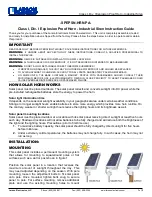
MODE:             HLPC

+

01D543B

INPUT:            3PH380V50Hz/60Hz
OUTPUT:        3PH380V4.0A1.5KW

Freq Range:     0.1-600Hz

HLP   ELECTRONICS  CO.,  LTD

Type:HLP    C

+  

  01D5    43     B

Hardware Version
Voltage Rating,

43 means 3-phase380V

Inverter Capacity,

01D5 means 1.5KW
Series No.
Trade Mark

● Check if there is something wrong on the inner parts, wiring 

and circuit board.

● Check if each terminal is tightly locked andif there is any 

foreign article insie the inverter.

● Check if the operator buttons are all right.

● Check if the optional components you ordered is contained in 

it.

● Check if there is a certificate of qualification and a warranty 

card.

( 2 ) Nameplate Information of HLP-C

+

 Series

Summary of Contents for Holip HLP-C+ Series

Page 1: ......

Page 2: ......

Page 3: ...ge and Installation 10 1 Storage 10 2 Installation Locationand Environment 10 3 Installation Space and Direction 10 Wiring 12 1 Main Circuit Schematic Diagram 12 2 Terminals Description 13 3 Basic Con...

Page 4: ...ance 80 2 Periodical Inspection and Maintenance items 80 3 Fault indication and troubleshooting 81 4 Faults and Analysis 85 Selection of Peripheral Devices and Disposition 88 1 Options 88 2 Dispositio...

Page 5: ...electronic product it must be installed tested and adjusted with parameters by specialized engineering persons of motor The marks of and other simbols in the manual remind you of the safety and preve...

Page 6: ...re subject to the effect and damage of static electricity Donn t touch the main circuit boards Installation testing and maintenance must be performed by qualified professional personnel The inverter s...

Page 7: ...means 1 5KW Series No Trade Mark Check if there is something wrong on the inner parts wiring and circuit board Check if each terminal is tightly locked andif there is any foreign article insie the inv...

Page 8: ...inals never mixed with U V W terminals Be sure that the wiring of the main circuit is correct Otherwise it will cause damages of the inverter when the power is delivered to it Do not carry the front c...
Page 9: ...e inverter in a space with explosive gas to avoid the risk of explosion If the inverter is used at or above 1000m above seal level the cooling efficiency will be worse so please run it by changing dow...

Page 10: ...s connected to the front end of input of the inverter to control its starting and stopping Generally it is required to control it through FOR or REV terminals Special attention should be paid to its u...

Page 11: ...speed to higher speed Do not check the signals on circuit boards while the inverter is running to avoid danger Be careful when changing the inverter settings The inverter has been adjusted and set be...

Page 12: ...PWM Input Power 400V class 345 440V 230V class 170 230V Range 0 1 600 0Hz Acuracy Digital 0 01 10 40 Analogue 0 1 25 10 Setting Resolution Digital 0 1Hz Analogue 1 of Max Operating Frequency Output Re...

Page 13: ...earch PLC traverse function drawing control auto energy savings carrier adjustable by max 16KHz etc 4 Ddigits Display Status Lamp Display frequency current revolution voltage counter temperature press...

Page 14: ...electrolytic capacity If it needs to be stored for long time be sure to power it one time within a yearand the power on time should be at least above five hours When powered In input the voltage must...

Page 15: ...d under the inverter bottom base and install again If the inverter is installed on a loose surface stress may cause damage in main circuit so as to damage the inverter The inverter should be installed...

Page 16: ...nterrupter Use one of anti high harmonic Magnetic contactor Note Do not use the magnetic contactor as the power supply on off button for the inverter AC reactor It is recommended to install a AC react...

Page 17: ...h single three phase single phase connected to any two phases U V W Output terminals to motor P P r External braking resistor terminals E Ground terminals the third kind of grounding for 230V and spec...

Page 18: ...e terminals must be connected correctly as the following wiring circuit diagrams Symbol Function Description Factory setting 10 Power supply for analog freqency 10V VI A n a l o g f r e q u e n c y re...

Page 19: ...and ground the shield layer or two ends of wire tube Be sure to install a No Fuse Breaker NFB between the power supply and the input terminals R S T If using ground fault circuit interrupter please ch...

Page 20: ...lease change it to a special AC motor for the inverter or add a reactor on the side of the inverter Please lower the carrier frequency if there is longer distance betweent the inerter and the motor Be...

Reviews: