background image

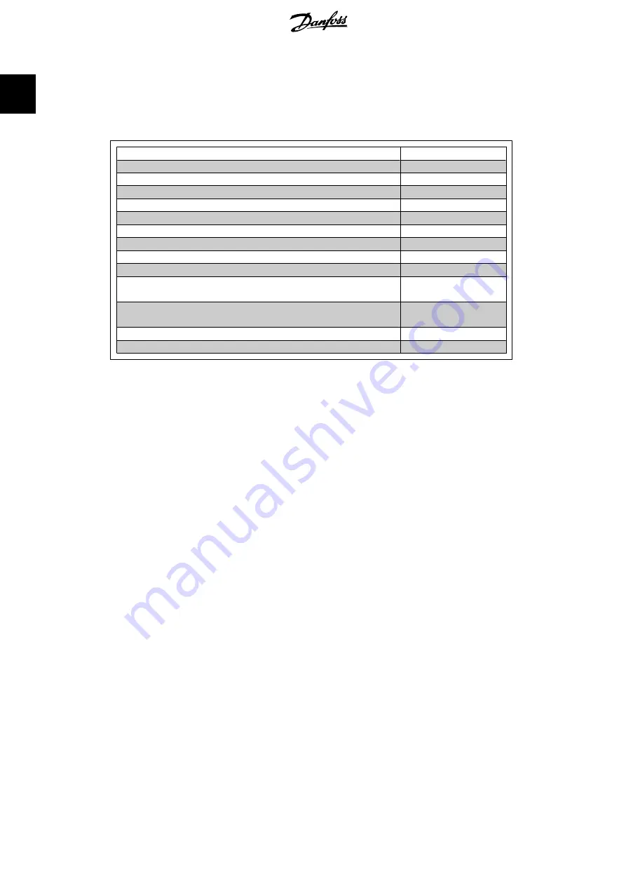
1.8. Available Literature

The following literature is available for the FC 100, 200 and 300 series.

Title

Literature no.

VLT HVAC Drive FC 100 Operating Instructions

MG.11.AX.YY

VLT HVAC Drive FC 100 Design Guide

MG.11.BX.YY

VLT HVAC Drive FC 100 Programming Guide

MG.11.CX.YY

VLT AQUA Drive FC 200 Operating Instructions

MG.20.NX.YY

VLT AQUA Drive FC 200 Design Guide

MG.20.MX.YY

VLT AQUA Drive FC 200 Programming Guide

MG.20.OX.YY

VLT AutomationDrive FC 300 Operating Instructions

MG.33.AX.YY

VLT AutomationDrive FC 300 Design Guide

MG.33.BX.YY

VLT AutomationDrive FC 300 Programming Guide

MG.33.MX.YY

VLT AutomationDrive FC 100, 200 and 300 PROFIBUS Operating
Instructions

MG.33.CX.YY

VLT AutomationDrive FC 100, 200 and 300 DeviceNet Operating In-
structions

MG.33.DX.YY

VLT AutomationDrive FC 300 MCT 10 Software Dialogue

MG.33.EX.YY

PROFIBUS DP V1 Design Guide

MG.90.EX.YY

X = Revision number
Y = Language code
Please also refer to 

www.danfoss.com/drives

 for frequently asked questions and additional infor-

mation.

1. Introduction

FC 100/ 200/ 300 DeviceNet

10


 MG.33.D3.02 - VLT

®

 is a registered Danfoss trademark 


1

Summary of Contents for FC 100 Series

Page 1: ...Modes 23 I O Assembly Instances 25 Process Data 25 ODVA Control Profile 27 Danfoss FC Control Profile 32 5 How to Access the Parameters 39 Explicit Messages 39 Object Classes 39 DeviceNet Object Class...

Page 2: ...Contents Illustration Illustration 1 1 9 Illustration 2 1 13 Contents FC 100 200 300 DeviceNet 2 MG 33 D3 02 VLT is a registered Danfoss trademark...

Page 3: ...Contents Table Table 8 1 LED Module Status MS 73 Table 8 2 LED Network Status NS 74 FC 100 200 300 DeviceNet Contents MG 33 D3 02 VLT is a registered Danfoss trademark 3...

Page 4: ...1 Introduction FC 100 200 300 DeviceNet 4 MG 33 D3 02 VLT is a registered Danfoss trademark 1...

Page 5: ...this manual Danfoss A S makes no warranty or representation either express or implied with respect to this documen tation including its quality performance or fitness for a particular purpose In no e...

Page 6: ...alue ETR warning Note The function is initialised at 1 16 x rated motor current and rated motor frequency For the North American market The ETR functions provide class 20 motor overload protection in...

Page 7: ...4 V DC load sharing linkage of DC intermediate circuit as well as the motor connection for kinetic back up Please refer to the relevant Operating Instructions for further safety guidelines FC 100 200...

Page 8: ...ng peer to peer communication Up to 63 nodes in a multi drop network topology are supported and communication options can be powered directly from the bus using the same cable for communication Nodes...

Page 9: ...rein fully respected 1 6 Hardware These operating instructions relate to the DeviceNet option type no 130B1102 and 130B1201 1 7 Background Knowledge The Danfoss DeviceNet is designed to communicate wi...

Page 10: ...300 Operating Instructions MG 33 AX YY VLT AutomationDrive FC 300 Design Guide MG 33 BX YY VLT AutomationDrive FC 300 Programming Guide MG 33 MX YY VLT AutomationDrive FC 100 200 and 300 PROFIBUS Oper...

Page 11: ...nel LED Light Emitting Diode LSB Least Significant Bit MAC ID Media Access Control IDentifier MAV Main Actual Value MRV Main Reference Value MSB Most Significant Bit N A Not Applicable ODVA Open Devic...

Page 12: ...2 How to Install FC 100 200 300 DeviceNet 12 MG 33 D3 02 VLT is a registered Danfoss trademark 2...

Page 13: ...meters 820 ft 78 meters 256 ft 500k baud 100 meters 328 ft 39 meters 128 ft 2 1 2 Cable Specifications The cable used should be according to ODVA specifications Be aware that the ODVA Flat Cable is an...

Page 14: ...iceNet communication cable must be kept away from motor and brake resistor cables to avoid coupling of high frequency noise from one cable to the other Normally a distance of 200 mm 8 inches is suffic...

Page 15: ...ground at only one point on the network NB Please note that this recommen dation conflicts with the correct EMC installation 2 1 6 Earth Connection It is important that all stations connected to the D...

Page 16: ...istors should be installed at each end of the bus line The resistors must be mounted between terminal 2 CAN_L and terminal 4 CAN_H and should have the fol lowing specification 121 Ohm 1 Metal film 1 4...

Page 17: ...ing either up or down The cable up position is often most suitable when several frequency con verters are installed side by side in a rack as this position permits shorter cable lengths Push the field...

Page 18: ...3 How to Configure the System FC 100 200 300 DeviceNet 18 MG 33 D3 02 VLT is a registered Danfoss trademark 3...

Page 19: ...s 20 OFF ON OFF ON OFF OFF Ex address 35 ON OFF OFF OFF ON ON NB Switch off the power supply before changing the hardware switches The address change will come into effect at the next power up and can...

Page 20: ...ging the hardware switches The baud rate change will come into effect at the next power up and can be read in par 10 01 Baudrate select 3 1 6 Setting the DeviceNet Baud Rate via Par 10 01 Baudrate se...

Page 21: ...cally detect whether a fieldbus option is installed in slot A and set par 8 02 Control Word Source to Option A If an option is added to changed in or removed from an already commissioned drive it will...

Page 22: ...4 How to Control the Frequency Converter FC 100 200 300 DeviceNet 22 MG 33 D3 02 VLT is a registered Danfoss trademark 4...

Page 23: ...slaves answers by sending a poll re sponse to the master The master can control and monitor the frequency converter by poll ing the DeviceNet or Danfoss objects I O In stances POLLED I O Master slave...

Page 24: ...connection object Class Code 0x05 To prevent the device from producing heavy network traffic if a value changes frequently the Production Inhibit Time an attribute of the connection object is defined...

Page 25: ...e I O Instance 101 151 in par 10 10 Process Data Type Selection This will change the I O size to four words in the input and output area This selection uses the Danfoss specific profile for the Contro...

Page 26: ...4 How to Control the Frequency Converter FC 100 200 300 DeviceNet 26 MG 33 D3 02 VLT is a registered Danfoss trademark 4...

Page 27: ...set 03 04 05 Net Ctrl 06 Net Ref 07 15 Explanation of the Bits Bit 0 Run Fwd Bit 0 0 means that the VLT frequency converter has a stop command Bit 0 1 leads to a start command and the VLT frequency c...

Page 28: ...1 Reference is from DeviceNet NB Please note that changes will affect parameters 3 15 to 3 17 Reference source X For the Speed reference see section Bus Speed Reference Value under Instances 20 70 an...

Page 29: ...n Bit 2 Running 1 Bit 2 0 means that the drive is not in one of these states or that Run 1 is not set Bit 2 1 means that the drive state attribute is enabled or stopping or that Fault Stop and bit 0 R...

Page 30: ...1 means that the drive and reference speeds are equal Bit 8 15 State attribute Instance 71 only Represents the state attribute of the drive as indicated in the table to the right Bit Num ber Meaning 8...

Page 31: ...ce Note that if the bus speed reference is negative and the control word contains a run reverse signal the drive will run clockwise is Example Par 1 25 Motor Nominal Speed 1420 RPM Par 1 23 Motor Freq...

Page 32: ...ction Reset 08 No function Jog 09 Ramp 1 Ramp 2 10 Data invalid Data valid 11 No function Relay 01 active 12 No function Relay 04 active 13 Parameter set up Selection lsb 14 Parameter set up Selection...

Page 33: ...inputs parameters 5 10 to 5 15 programmed to Speed up and Speed down NB If Hold output is active only the following can stop the frequency converter Bit 03 Coasting stop Bit 02 DC braking Digital inp...

Page 34: ...activated Bit 11 1 Relay 01 activated provided Con trol word bit 11 has been chosen in par 5 40 Function Relay Bit 12 Relay 04 Bit 12 0 Relay 04 has not been activated Bit 12 1 Relay 04 has been acti...

Page 35: ...1 Drive ready Bit 01 1 The frequency converter is ready for operation but there is an active coasting com mand via the digital inputs or via serial communication Bit 02 Coasting stop Bit 02 0 The freq...

Page 36: ...the motor is not running Bit 11 1 means that the frequency converter has a start signal or that the output frequency is greater than 0 Hz Bit 12 Drive OK stopped auto start Bit 12 0 means that there...

Page 37: ...MAX refMAX 16384 C000 Hex 16384 4000 Hex 100 100 4 5 4 Actual Output Frequency under Instances 100 150 and 101 151 The value of the actual output frequency of the frequency converter is transmitted in...

Page 38: ...5 How to Access the Parameters FC 100 200 300 DeviceNet 38 MG 33 D3 02 VLT is a registered Danfoss trademark 5...

Page 39: ...take place via dynamically established lower prioritized connections 5 2 Object Classes The following Standard DeviceNet objects can be accessed Class ID 01h Identity Object Class ID 10h Parameter Gr...

Page 40: ...guration and status of the DeviceNet connection The attributes supported for this class are listed below 5 3 4 Class ID 0x03 Attrib ute Access Name Data type Min Max Units Default Description 1 Get Se...

Page 41: ...ile Instance 21 71 70 Get 2 Words DeviceNet AC DC Profile Instance 20 70 71 Get 2 Words DeviceNet AC DC Profile Instance 21 71 100 Set 2 Words Danfoss specific no PCD Words Instance 100 150 101 Set 4...

Page 42: ...received across this connection 9 Get Set Expected Package Rate UINT Defines value used in Transmission Trigger Tim er and Inactivity Watchdog timer 12 Get Watchdog timeout action USINT Defines how to...

Page 43: ...across this connection 9 Get Set Expected Package Rate UINT Defines value used in Transmission Trigger Tim er and Inactivity Watchdog timer 12 Get Watchdog timeout action USINT Defines how to handle...

Page 44: ...er and Inactivity Watchdog timer 12 Get Watchdog timeout action USINT Defines how to handle Inactivity Watchdog timeout 13 Get Produced Connec tion Path Length UINT Number of Bytes in the produced con...

Page 45: ...able text string representing pa rameter name 10 Get Full Min value Data type1 Min valid value 11 Get Full Max value Data type1 Max valid value 12 Get Full Default value Data type1 Parameters default...

Page 46: ...up In stance Name max 16 characters 0 1 O P E R A T I O N D I S P L 1 2 L O A D M O T O R 2 3 B R A K E S 3 4 R E F E R E N C E R A M P S 4 5 L I M I T S W A R N I N G S 5 6 D I G I T A L I N O U T 6...

Page 47: ...or Current rating from motor nameplate 1 24 7 Get set Rated voltage UNIT 200 500 volt Drive dependent Base Voltage rating from motor nameplate 1 22 8 Get set Rated power UDINT 0 18500 Watt Drive depen...

Page 48: ...ng 1 Bool 0 1 0 0 Other state 1 Enable and Run 1 or Stopping and Running 1 or Fault Stop and Running 1 8 Get Running 2 Bool 0 1 0 0 Other state 1 Enable and Run 2 or Stopping and Running 2 or Fault St...

Page 49: ...0 Drive not at reference 1 Drive at reference 4 Get Set Net REf Bool 0 1 1 0 Set reference at non DeviceNet refer ence 1 Set reference at DeviceNet reference 6 Get Set Drive Mode USINT 0 1 1 0 Vendor...

Page 50: ...escription The Danfoss VLT DeviceNet uses Instance 1 only so always leave this at the value of 1 Attribute Description The attributes for the FC 100 200 or 300 pa rameter are the last 2 two digits of...

Page 51: ...this feature at the same time incorrect data may be gener ated 5 5 1 Example Write 16 10 in index 2 in par 10 12 Process Data Config Read First set up the index pointer in par 10 30 Array Index In th...

Page 52: ...6 Parameters FC 100 200 300 DeviceNet 52 MG 33 D3 02 VLT is a registered Danfoss trademark 6...

Page 53: ...cy converter detects a change in the configuration sets par 8 02 back to default setting FC RS485 and the frequency converter then trips If an option is installed after initial power up the setting of...

Page 54: ...up upon reestablishment of communication follow ing a control word time out If communication resumes causing the time out situation to disappear par 8 05 End of time out Function defines whether to re...

Page 55: ...for DeviceNet 8 10 Control Word Profile Option Function 0 FC profile 5 ODVA When this parameter is set to 0 FC profile Instances 100 150 and 101 151 are selectable in par 10 10 When 3 ODVA profile is...

Page 56: ...erial communication port or fieldbus option 2 Logic AND Activates Start command via the fieldbus serial communication port AND additionally via one of the digital inputs 3 Logic OR Activates Start com...

Page 57: ...3 Logic OR Activate the set up selection via the fieldbus serial communica tion port OR via one of the digital inputs NB This parameter is active only when par 8 01 Control Site is set to 0 Digital an...

Page 58: ...01 Baud Rate Select Option Function 16 10 Kbps 17 20 Kbps 18 19 50 Kbps 100 Kbps 20 125 Kbps 21 250 Kbps 22 500 Kbps Select the fieldbus transmission speed The selection must cor respond to the trans...

Page 59: ...options 2 and 3 are available Instances 100 150 and 101 151 are Danfoss specific Instances 20 70 and 21 71 are ODVA specific AC Drive profiles For guidelines in telegram selection please refer to the...

Page 60: ...PCD 4 Write to MCO 34 05 PCD 5 Write to MCO 34 06 PCD 6 Write to MCO 34 07 PCD 7 Write to MCO 34 08 PCD 8 Write to MCO 34 09 PCD 9 Write to MCO 34 10 PCD 10 Write to MCO Select the process write data...

Page 61: ...Energy 2 min 16 34 Heatsink Temp 16 35 Inverter Ther mal 16 38 SL Control State 16 39 Controlcard Temp 16 50 External Refer ence 16 51 Pulse Refer ence 16 52 Feedback Unit 16 53 Digi Pot Refer ence 16...

Page 62: ...ad from MCO 34 22 PCD 2 Read from MCO 34 23 PCD 3 Read from MCO 34 24 PCD 4 Read from MCO 34 25 PCD 5 Read from MCO 34 26 PCD 6 Read from MCO 34 27 PCD 7 Read from MCO 34 28 PCD 8 Read from MCO 34 29...

Page 63: ...e DeviceNet Operating Instruc tions MG 33 DX YY for further information Bit Meaning 0 Bus not active 1 Explicit connection timeout 2 I O connection 3 Retry limit reached 4 Actual is not updated 5 CAN...

Page 64: ...lter out bits in PCD 3 that should not be sent if they change 10 23 COS Filter 4 Range Function 65535 0 65535 Sets up the filter mask for PCD 4 When operating in COS Change Of State it is possible to...

Page 65: ...ether parameter data re ceived via the DeviceNet option should always be stored in non volatile memory 16 90 Alarm Word Range Function 0 0 FFFFFFFF View the alarm word sent via the serial communicatio...

Page 66: ...90 Bus Jog 1 Speed 100 rpm 0 par 4 13 67 6 8 91 Bus Jog 2 Speed 200 rpm 0 par 4 13 67 6 10 00 CAN Protocol DeviceNet 1 0 1 5 10 01 Baud Rate Select 125 Kbps 20 20 22 5 10 02 MAC ID 63 0 63 0 5 10 05 R...

Page 67: ...Standardized value 16 bit 35 Bit sequence 41 Byte 42 Word 6 3 2 Conversion Index This number refers to a conversion figure used when writing or reading to parameters Conversion index Conversion factor...

Page 68: ...7 Application Examples FC 100 200 300 DeviceNet 68 MG 33 D3 02 VLT is a registered Danfoss trademark 7...

Page 69: ...l motor torque PCD 4 is set up to monitor the state of an external sen sor via the process signal digital input The sensor is connected to digital input 18 An external device is also controlled via co...

Page 70: ...us 1 8 54 Reversing select Logic AND 2 8 55 Set up select Bus 1 8 56 Preset reference select Bus 1 10 01 Baud rate select set to match other DeviceNet stations 10 02 MAC ID set desired station address...

Page 71: ...tput ad dress 0 0 0 15 0 16 0 31 1 0 1 15 1 16 1 31 Set up Control word Reference Not used Not used FC 100 200 300 DeviceNet 7 Application Examples MG 33 D3 02 VLT is a registered Danfoss trademark 71...

Page 72: ...8 Troubleshooting FC 100 200 300 DeviceNet 72 MG 33 D3 02 VLT is a registered Danfoss trademark 8...

Page 73: ...Off There is no power applied to the option Device opera tional Green The DeviceNet option is operating in nor mal condition Standby Green The DeviceNet option needs commission ing due to configurati...

Page 74: ...tion is on line but not allocated to a master On line and con nected Green The DeviceNet option is on line and con nected to a master Connection time out Red One or more I O connections are in time ou...

Page 75: ...Red 24 V Check 2 Is the 24V network voltage applied Check 3 Is the correct EDS file installed Download the correct EDS file from http www danfoss com drives Check 4 Is the bus connection terminated a...

Page 76: ...is selected the terminals will control the Coast and DC Brake functions Par 8 50 51 52 setting Digital Input 0 Terminal Bit 02 03 04 Function 0 0 Coast DC brake Q Stop 0 1 Coast DC brake Q Stop 1 0 No...

Page 77: ...03 04 Function 0 0 Stop Anti clockwise 0 1 Stop Anti clockwise 1 0 Stop Anti clockwise 1 1 Start Clockwise If Logic OR 3 is selected activation of one signal will activate the function Par 8 53 54 se...

Page 78: ...erminal Bit 00 01 13 14 Function Msb Lsb Msb Lsb Preset ref Set up no 0 0 0 0 1 0 0 0 1 1 0 0 1 0 1 0 0 1 1 1 0 1 0 0 1 0 1 0 1 2 0 1 1 0 1 0 1 1 1 2 1 0 0 0 1 1 0 0 1 1 1 0 1 0 3 1 0 1 1 3 1 1 0 0 1...

Page 79: ...r voltage 8 Major Recoverable 00000800 DC link over voltage 7 Major Recoverable 00001000 Short circuit 16 Major Unrecoverable 00002000 Inrush fault 33 Major Recoverable 00004000 Mains phase loss 4 Maj...

Page 80: ...ult condition After the cause for the alarm has been cleared the master will have to acknowledge the alarm message for the frequency converter to start operating again A warning on the other hand may...

Page 81: ...Devicenet Connection 16 Devicenet Object Classes 39 Devicenet Termination 16 Drive Will Not Respond To Control Signals 76 Drop Cable 16 E Earth Connection 15 Eds File 21 Emc Precautions 14 I I o Asse...

Page 82: ...S Safety Note 6 Setting The Devicenet Address 19 Setting The Devicenet Baud Rate 20 Start Select 8 53 56 T Topology 9 V Vlt Parameters 21 W Warning Parameter 10 13 63 Warning Word 79 Warning Word 16 9...

Reviews: