AK-CH
650
Capacity
controller RS8ER302 © Danfoss 2016-02
53
Configuration - continued
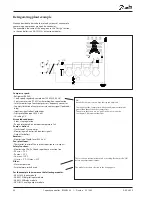
Press the +-button to go on to the
next page
5. Set values for capacity of the
compressors
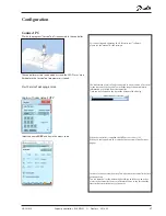
Press the +-button to go on to the
next page
6. Set values for main step and any
unloaders
Press the +-button to go on to the
next page
7. Set values for safe operation
In our example we select:
- Safety limit for discharge
temperature = 120°C
- Safety limit for high condensing
pressure = 50°C
- Safety limit for low suction
pressure = -10°C
- Alarm limit for min. and max.
superheat, respectively = 5 and
35 K.
In our example we select:
- Speed-controlled compressor of
30 kW (compressor 1)
- 3 compressors of 15 kW
In our example there are no
unloaders and hence no changes.
Pump down limit (-80 to +30 °C)
Select pump down limit
VSD min speed (0.5 – 60.0 Hz)
Minimum allowed speed before stop of Variable Speed drive
(Low load condition)
VSD start speed (20.0 – 60.0 Hz)
Minimum speed for start of Variable speed drive (Must be set
higher than “VSD Min. Speed Hz”)
VSD max speed (40.0 – 120.0 Hz)
Highest permissible speed for the compressor motor
VSD safety monitoring
Select this if input for monitoring of the frequency converter
is required.
Start delay first compressor (5-600 sec.)
To ensure brine flow before startup, a delay before start of
the first compressor can be entered.
Load shed limits
Select how many load shedding inputs are required
Load shed limit 1
Set max capacity limit for load shed input 1
Load shed limit 2
Set max capacity limit for load shed input 2
Override limit Po
Any load below the limit value is freely permitted. If the P0
exceeds the value, a time delay is started. If the time delay
expires, the load limit is cancelled
Override delay 1
Max. time for capacity limit, if P0 is too high
Override delay 2
Max. time for capacity limit, if P0 is too high
Advanced control settings
Select whether the advanced capacity control settings
should be visible
Kp S4
Amplification factor for P0 regulation (0.1 – 10.0)
Min. capacity change (0 – 100 %)
Minimum change in requested capacity that will result in cut
in/out of compressors.
Initial start time (15 – 900 s)
The time after start-up where the cut-in capacity is limited to
the first compressor step.
Unloading mode
Select whether one or two capacity controlled compressors
are allowed to be unloaded at the same time at decreasing
capacity
5 - Compressors
In this screen the capacity distribution between the com-
pressors is defined.
Capacities that need to be set depend upon the “compressor
application” and “Step control mode” that has been selected.
Nominal capacity (0.0 – 100000.0 kW)
Set the nominal capacity for the compressor in question.
For compressors with variable speed drive the nominal
capacity must be set for the mains frequency (50/60 Hz)
Unloader
Number of unload valves for each compressor (0-3)
6 - Capacity distribution
The installation is dependent on the combination of com-
pressors and coupling pattern.
Main step
Set the nominal capacity of the main step (Set the percent-
age of the relevant compressor’s nominal capacity) 0 -
100%.
Unload
Readout of the capacity on every unloading 0-100%.
7 - Safety
Emergency cap. day
The desired cut-in capacity for daily use in the case of emer-
gency operations resulting from error in the suction pressure
sensor/ media temperature sensor.
Emergency cap. night
The desired cut-in capacity for night operations in the case
of emergency operations resulting from error in the suction
pressure sensor/ media temperature sensor.
Sd max limit
Max. value for discharge gas temperature
10 K below the limit, the compressor capacity should be

