90
Capacity
controller RS8ER302 © Danfoss 2016-02
AK-CH
650
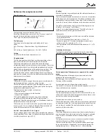
Oil pressure cutout
Overload current cut-out
Motor temperature cutout
Discharge temp. cutout
Output pressure cut-out
General protection
Common safety circuit
A common safety signal can also be received from the whole suction group. All
compressors will be cut out when the safety signal cuts out.
General safety circuit
Safety functions
Signal from the compressor’s safety controls
The controller can monitor the status of each compressor’s safety
circuit. The signal is taken directly from the safety circuit and
connected to an input.
(The safety circuit must stop the compressor without involving the
controller).
If the safety circuit is cut out the controller will cut out all
output relays for the compressor in question and give an alarm.
Regulation will continue with the other compressors.
Time delays with safety cut-out:
In connection with safety monitoring of a compressor it is possible
to define two delay times:
Cut-out delay time: Delay time from alarm signal from the
safety circuit until the compressor outlet cuts out (note that the
delay time is common to all security inlets for the compressor
concerned)
Safety re-start time: The minimum time a compressor must be OK
after a safety cut-out until it may start again.
Monitoring of superheat
This function is an alarm function which continuously receives
measured data from suction pressure P0 and suction gas Ss.
If superheat is registered which is lower or higher than the set
limit values, an alarm will be given when the time delay has
passed.
Monitoring of max. discharge gas temperature (Sd)
The function gradually cuts out compressor steps if the discharge
temperature becomes higher than permitted. The cutout limit can
be defined in the range from 0 to +195°C.
The function is started at a value that is 10 K below the set value.
At this point the entire condenser capacity is cut in at the same
time as 33% of the compressor capacity is cut out (but minimum
one step). This is repeated every 30 seconds. The alarm function is
activated.
If the temperature rises to the set limit value all compressor steps
are immediately cut out.
The alarm is cancelled and renewed cutin of compressor steps is
permitted when the following conditions are met:
- the temperature has dropped to 10 K below the limit value
- the time delay prior to restart has been passed. (see later)
Normal condenser control is permitted again when the
temperature has dropped to 10 K below the limit value.
Monitoring of min. suction pressure (P0)
The function promptly cuts out all compressor steps if the suction
pressure becomes lower than the permitted value.
The cutout limit can be defined in the range from -120 to +30°C.
The suction is measured with pressure transmitter P0.
At cutout the the alarm function is activated:
The alarm is cancelled and renewed cutin of compressor steps is
permitted when the following conditions are met:
- the pressure (temperature) is above the cutout limit
- the time delay has elapsed (see later).
(On startup of the first compressor it is possible to delay the func-
tion so that cut-out can be avoided.)
Monitoring of max. condensing pressure (Pc)
The function cuts in all condenser steps and cuts out compressor
steps one by one if the condensing pressure becomes higher than
permitted. The cutout limit can be defined in the range from –30
to +100°C.
The condensing pressure is measured with pressure transmitter
Pc.
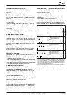
If a low-pressure switch is placed in the
safety circuit it must be placed at the end of
the circuit. It must not cut out the DI signals.
(There is a risk that the regulation will be-
come locked and that it will not start again).
This also applies to the example below.
If an alarm is needed which also monitors
the low-pressure thermostat, a “general
alarm” can be defined (an alarm that does
not affect the control).
See the following section “General monitor-
ing functions”.
Extended safety circuit
Instead of a general monitoring of the safety circuit this monitoring function
can be extended. In this way a detailed alarm message is issued which tells you
which part of the safety circuit has dropped out.
The sequence of the safety circuit must be established as shown, but not all of
them need necessarily be used.


