VLT
®
5000/5000 Flux/6000 HVAC/8000 AQUA PROFIBUS
MG.90.D1.02 – VLT is a registered Danfoss trademark
21
Bit 10, Not in operating range/Frequency limit OK
In the case of bit 10 = “0”, the output frequency is
outside the limits set in parameter 225 and para-
meter 226 (Warnings: frequency low or frequency
high).
In the case of bit 10 = “1”, the output frequency is
within the indicated limits.
Bit 11, No operation/Operation
In the case of bit 11 = “0”, the motor does not turn.
In the case of bit 11 = “1”, the frequency converter
has a start signal, or the output frequency is higher
than 0 Hz.
Bit 12, VLT OK/Stopped, autostart
In the case of bit 12 = “0”, there is no temporary
overloading of the inverter.
In the case of bit 12 = “1”, the inverter has stop-
ped due to overloading. However, the frequency
converter has not switched off (trip) and will start
again after the overloading has ended.
Bit 13, Voltage OK/Limit exceeded
In the case of bit 13 = “0”, the voltage limits of the
frequency converter are not exceeded.
In the case of bit 13 = “1”, the direct voltage in the
intermediate circuit of the frequency converter is
too low or too high.
Bit 14, Moment OK/Limit exceeded
In the case of bit 14 = “0”, the motor current is be-
low the moment limit selected in parameter 221.
In the case of bit 14 = “1”, the moment limit selec-
ted in parameter 221 is exceeded.
Bit 15, Timer OK/Limit exceeded
In the case of bit 15 = “0”, the timers for the ther-
mal motor protection and thermal VLT protection
(description on page 67) have not exceeded 100%.
In the case of bit 15 = “1”, one of the timers has
exceeded 100%.
■
■
■
■
■
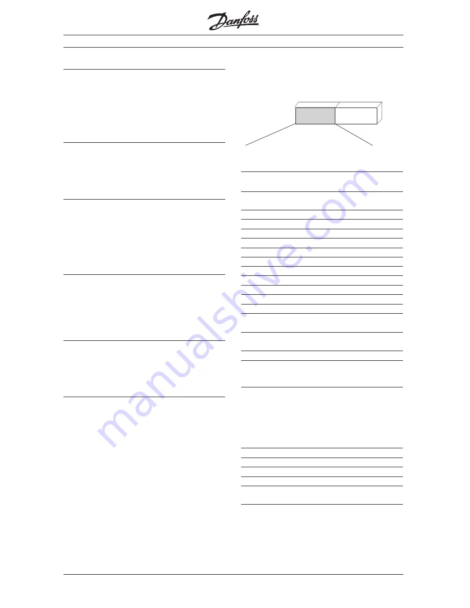
Control word according to VLT standard
(Parameter 512 = FC Drive)
The control word is used to send commands from a
master (e.g. a PC) to a slav
e.
Master
➝
Slave
15 14 13 12 11 10 9 8 7 6 5 4 3 2 1 0 Bit no.
Bit Bit = 0
Bit =1
00 Reference value external
selection lsb
01 Reference value external
selection msb
02 DC brake
Ramp
03 Freewheel
No freewheel
04 Quick stop
Ramp
05 Holding
Ramp possible
06 Ramp stop
Start
07 Without function
Reset
08 Without function
Jog
09 Ramp 1
Ramp 2
10 Data not valid
Valid
11 Without function
Relay 01 active
12 Without function
Relay 04 active
13 Parameter setup
selection lsb
14 Parameter setup
selection msb
15 Without function
Reversion
Bit 00/01
The bits 00 and 01 are used to choose between
the four preprogrammed reference values (para-
meters 215-218)
according to the following table:
Progr. ref. val.
Parameter
Bit 01
Bit 00
1
215
0
0
2
216
0
1
3
217
1
0
4
218
1
1
Bit 02, DC brake
Bit 02 = “0” leads to direct voltage braking and
stop. Braking current and duration are set in para-
meter 125 and 126.
Bit 02 = “1” results in
Ramp.
Control
word
Bus
reference
Control word / Status word


