background image

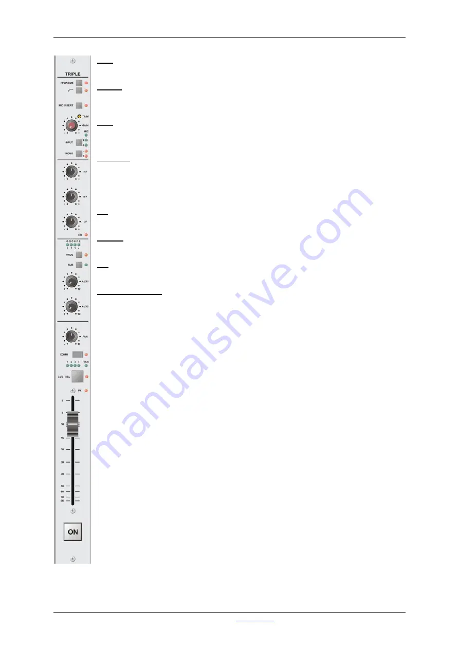
Triple Input Stereo Module 

AirMax from D&R - Phone: +31 294 418014 - E-Mail: 

[email protected]


- 10 - 

PAN


Allows adjustment between the left and right channel outputs. 
 

COMM


The COMM switch enables communication between this channel and anyone who has 
access to the COMM bus at the same time. 
 

VCA 

These leds indicate if and by which VCA master this module is currently controlled.  
The VCA led gives an indication of the amplitude of the VCA control voltage. 
 

CUE/SEL


CUE/SEL allows for pre-fade listening of the channel with the fader closed.  
The CUE switch also acts as a SEL(ECT) switch for the assignment of the module to a 
stereo GROUP or VCA master. 
In configuration mode this switch is used to program the modules identity. 
 

PK 

The PK led acts as a peak led on the input signals. 
 

FADER


The linear fader controls a VCA and thereby the module's overall level. 
 

ON


Channel ON/OFF switch. The associated LED will light when the ON switch is active. 
 

RIAA Plug-in PCB 

Optionally a RIAA Plug-in PCB can be inserted into the signal path of LINE B to directly 
connect a gramophone player to the input.

Summary of Contents for AIRMAX

Page 1: ...31 294 418014 E Mail info d r nl 1 AIRMAX User Manual Version 1 0 0 0 D R Electronica Weesp BV Rijnkade 15B 1382GS Weesp The Netherlands Phone 31 0 294 418014 Fax 31 0 294 416987 Website http www d r...

Page 2: ...s value suggestions from our clients once they have become familiar with their console We will certainly learn from your comments and very much appreciate your time doing this We are confident that yo...

Page 3: ...TION 22 9 3 GENERAL PURPOSE INPUT OUTPUT 23 10 MASTER MODULE 24 10 1 THE PROGRAM SECTION 24 10 2 THE CRM SECTION 25 10 3 GENERAL PURPOSE INPUT OUTPUT 26 11 STUDIO MODULE 27 11 1 GENERAL PURPOSE INPUT...

Page 4: ...Contents AirMax from D R Phone 31 294 418014 E Mail info d r nl 4 20 LIST OF TABLES 44 21 DECLARATION OF CONFORMITY 45 22 PRODUCT SAFETY 46 23 DISCLAIMER 49...

Page 5: ...hing any control or even thinking about hooking up the system We know that that is actually the first thing you want to do but please do NOT and discipline yourself to read the manual first The manual...

Page 6: ...gnments can be made for audio and VCA groups With a maximum of 8 studio modules the AirMax can be deployed in both small and large setups All studio modules have two phones sections and of course a mo...

Page 7: ...to the PROG ram output SUB The SUB switch assigns the signal in stereo to the SUB output AUX1 The AUX1 control adjusts the amount of signal send to the stereo AUX 1 bus AUX2 The AUX2 control adjusts...

Page 8: ...n off or both The module has four GPO s When properly connected to an AirMax patch panel all GPO s are connected to one of the Remote jack connectors between the Tip and Ring By opto isolated relays t...

Page 9: ...is currently selected MONO The MONO switch can convert an incoming signal into a mono signal or accept one and route it to both outputs of the module The associated LEDS indicate if mono is currently...

Page 10: ...age CUE SEL CUE SEL allows for pre fade listening of the channel with the fader closed The CUE switch also acts as a SEL ECT switch for the assignment of the module to a stereo GROUP or VCA master In...

Page 11: ...rMax patch panel all GPO s are connected to one of the Remote jack connectors between the Tip and Ring By opto isolated relays the GPO s are able to handle a maximum of 50 V at 200 mA GPI s can be set...

Page 12: ...e which input is currently selected MONO The MONO switch is used to make an incoming signal mono or accept one and route it to both outputs of the module The associated LEDS indicate if mono is curren...

Page 13: ...VCA led gives an indication of the amplitude of VCA control voltage CUE SEL CUE SEL allows pre fade listening of the channel with the fader closed The CUE switch also acts as a SEL ECT switch for the...

Page 14: ...cted to an AirMax patch panel all GPO s are connected to one of the Remote jack connectors between the Tip and Ring By opto isolated relays the GPO s are able to handle a maximum of 50 V at 200 mA GPI...

Page 15: ...ange from 1 kHz to off LC The LC control adjusts the12 dB per octave low cut filter in a range from off to 500 Hz FILTER The FILTER led indicates whether the HC LC filters are on or off GROUPS These l...

Page 16: ...switch also acts as a SEL ECT switch for the assignment of the module to a stereo GROUP or VCA master In configuration mode this switch is used to program the modules id PK The PK led acts as a peak...

Page 17: ...nnected to an AirMax patch panel all GPO s connect to one of the Remote jack connectors between the Tip and Ring By way of opto isolated relays the GPO s are able to handle a maximum of 50 V at 200 mA...

Page 18: ...2 or 6 dB at 10 kHz shelving MF Adjusts high mid frequencies with 12 or 6 dB at 1 kHz bell curve LF Adjusts the low frequencies with 12 or 6 dB at 60 Hz shelving EQ The EQ led indicates whether equali...

Page 19: ...o acts as a SEL ECT switch for the assignment of the module to a stereo GROUP or VCA Master In configuration mode this switch is used to program the modules identity PK The PK led acts as a peak led o...

Page 20: ...r both The module has four GPO s When properly connected to an AirMax patch panel all GPO s are connected to one of the Remote jack connectors between the Tip and Ring Opto isolated relays in the GPO...

Reviews: