background image


PC2-Comp Express 

Sapera LT 

 53 

Sapera Grab Demo 

Overview 

Program 

Start•All Programs•DALSA •Sapera LT•Demos•Grab Demo  

Program file 

\DALSA


Coreco\Sapera\Demos\Classes\vc\GrabDemo\Release\GrabDemo.exe 

Workspace 

\DALSA


Coreco\Sapera\Demos\Classes\vc\SapDemos.dsw  

.NET Solution 

\DALSA


Coreco\Sapera\Demos\Classes\vc\SapDemos_2003.sln  

Description 

This program demonstrates the basic acquisition functions included in the Sapera 
library. The program allows you to acquire images, either in continuous or in one-
shot mode, while adjusting acquisition parameters. The program code can be 
extracted for use within your own application.  

Remarks 

Grab Demo was built using Visual C++ 6.0 by means of the MFC library and is 
based on the Sapera standard API and Sapera C++ classes. See the Sapera User’s 
and Reference manuals for further information. 

Using the Grab Demo 

Server Selection  

Run Grab Demo: 

Start•All Programs•DALSA •Sapera LT•Demos•Grab Demo

.  


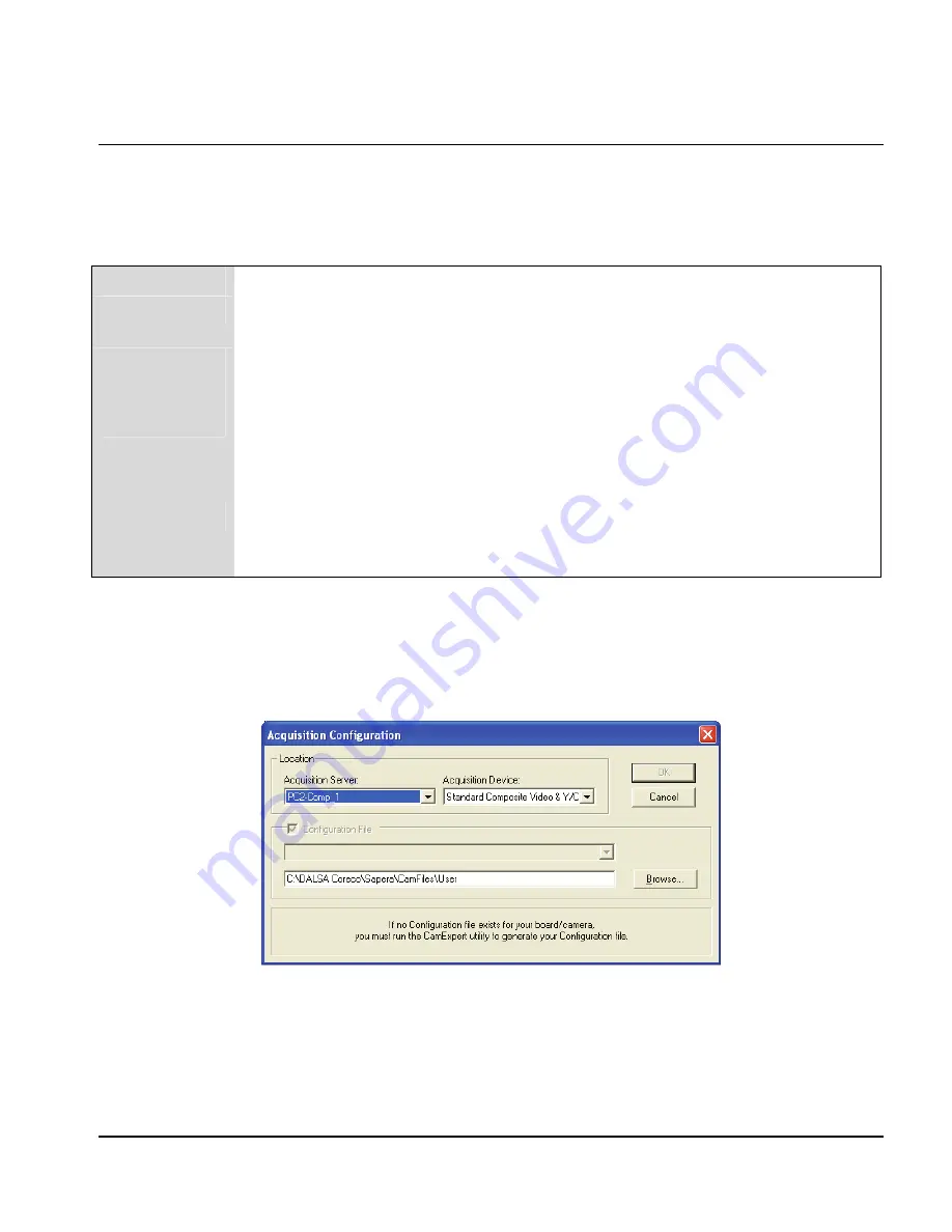
When executed, Grab Demo first displays the "Acquisition Configuration" window. The first drop-
down menu allows you to select any installed Sapera acquisition server (that is, installed DALSA 
acquisition hardware using Sapera drivers). The second drop-down menu allows you to select the 
available input devices present on the selected server.  

Summary of Contents for PC2-Comp Express OC-P2EM-COMP0

Page 1: ...DALSA 7075 Place Robert Joncas Suite 142 St Laurent Quebec H4M 2Z2 Canada http www dalsa com OC P2EM COMP0 PC2 Comp Express User s Manual Part number OC P2EM COMP0 Edition 2 01 ...

Page 2: ...ed herein is understood to be at the user s risk DALSA Corp assumes no liability whatsoever for the use of the products detailed in this document and reserves the right to make changes in specifications at any time and without notice Microsoft is a registered trademark Windows Windows XP Windows Vista and Windows 7 are trademarks of Microsoft Corporation All other trademarks or intellectual proper...

Page 3: ...VER 8 In a Windows XP Vista 7 System 8 Device Manager Firmware Loader 9 Firmware Update Automatic Mode 10 Firmware Update Manual Mode 10 Executing the Firmware Loader from the Start Menu 11 UPGRADING SAPERA LT OR ANY DALSA DEVICE DRIVER 11 Device Driver Upgrade Only 12 Sapera LT and Device Driver Upgrades 12 CONNECTING CAMERAS 13 TESTING ACQUISITIONS 15 TROUBLESHOOTING INSTALLATION PROBLEMS 15 Rec...

Page 4: ... 27 Acquisition Status 27 Chroma Present 27 Horizontal Sync Lock 27 Vertical Sync Lock 27 Transfer Events 28 End of Frame 28 End of Field 28 End of Odd Field 28 End of Even Field 28 End of Transfer 28 EXTERNAL TRIGGER 29 TRIGGER TO IMAGE RELIABILITY 30 Trigger Signal Validity 30 Acquisition Or Transfer Status 30 Supported Transfer Cycling Methods 31 TECHNICAL REFERENCE 33 HARDWARE SPECIFICATIONS 3...

Page 5: ... Messaging 42 SAPERA SERVER AND PARAMETERS 43 USING CAMEXPERT WITH PC2 COMP EXPRESS 47 CamExpert Example with a PAL Camera 47 Saving a Camera Configuration File 49 Overview of Sapera Acquisition Parameter Files ccf or cca cvi 50 Camera Interfacing Check List 51 A Note on Analog Camera Timing Relationships 51 Overview of Video Bandwidth and System Limitations 52 SAPERA GRAB DEMO 53 Overview 53 Usin...

Page 6: ...iv Contents PC2 Comp Express ...

Page 7: ...g the PC2 Comp Express Theory of Operation Detailing PC2 Comp Express features Technical Reference Hardware PC2 Comp Express specifications including connector pinout diagrams jumper and LED descriptions Sapera LT Sapera LT Server and Parameters Lists the Sapera LT servers available plus describes the Sapera LT parameters and values supported by PC2 Comp Express board Sapera Software Example Descr...

Page 8: ...mation visit the DALSA web site at http www dalsa com Using the Manual File names directories and Internet sites will be in bold text for example image2 bmp c Sapera http www imaging com Text that must be entered using the keyboard will be in typewriter style text for example c temp Menu and dialog actions will be indicated in bold text in the order of the instructions to be executed with each ins...

Page 9: ...plication 2 Current Sapera compliant board hardware drivers 3 Board and Sapera documentation compiled HTML help and Adobe Acrobat PDF formats OC SL00 0000000 optional Sapera Processing Imaging Development Library includes over 600 optimized image processing routines Contact Sales at DALSA PC2 Comp Express Cables Accessories Item Product Number PC2 Comp Express input cable OR B20C 4RGB0 4 Pin DIN t...

Page 10: ... Processing library PC2 Comp Express Features Half size single slot PCIe x1 form factor Six monochrome or composite video CV or 2 S video inputs AC coupled and 75Ω terminated Acquires from color or monochrome cameras Supports standard NTSC RS 170 PAL and CCIR camera formats Video controls allow brightness contrast hue and saturation adjustments Supports YUV 4 2 2 YUY2 and Mono 8 output pixel forma...

Page 11: ...5 PC2 Comp Express Functional Block Diagram Input MUX M1 CV1 Y1 M2 CV2 C1 M3 CV3 Y2 M4 CV4 C2 M5 CV5 M6 CV6 Decoder PCI controller PCIe x1 bus Image Buffer Local PCI bus 32 bit 66 MHz PCI to PCIe Bridge Figure 1 PC2 Comp Express Block Diagram ...

Page 12: ... display functionality and management plus easy to use application development wizards Sapera LT comes bundled with CamExpert an easy to use camera configuration utility to create new or modify existing camera configuration files Information and screen shots in this manual correspond to Sapera LT 5 2 Sapera Processing Library Supplied optionally Sapera Processing is a comprehensive set of C classe...

Page 13: ...p when a board is installed Sapera LT Library Installation Note to install Sapera LT and the PC2 Comp Express device driver log onto the workstation as an administrator or with an account that has administrator privileges The Sapera LT Development library or runtime library if application development is not being performed must be installed prior to the PC2 Comp Express device driver Insert the DA...

Page 14: ...er of the computer Windows will find the PC2 Comp Express and start its Found New Hardware Wizard Click on the Cancel button to close the Wizard Insert the DALSA Sapera CD ROM If AUTORUN is enabled on your computer the installation menu is presented Install the PC2 Comp Express driver If AUTORUN is not enabled use Windows Explorer and browse to the root directory of the CD ROM Execute launch exe t...

Page 15: ...page 9 When the installation is complete the following dialog box is displayed Device Manager Firmware Loader The Device Manager Firmware Loader program determines if the PC2 Comp Express requires a firmware update If firmware is required the dialog displays and it also allows the user to load specific firmware for the PC2 Comp Express Important In the vary rare case of firmware loader errors plea...

Page 16: ...nual mode to load firmware other then the default version or when in the case of multiple PC2 Comp Express boards in the same system each requires different firmware The figure below shows the Device Manager manual firmware screen Information on all installed PC2 Comp Express boards their serial numbers and their firmware components are shown A manual firmware update is made as follows Select the ...

Page 17: ...m is executed via the Windows Start Menu shortcut Start All Programs DALSA PC2 Comp Express Driver Update Firmware Upgrading Sapera LT or any DALSA Device Driver When installing a new version of Sapera LT or a DALSA device driver into a computer with a previous installation the current version must be first uninstalled Upgrade scenarios are described below ...

Page 18: ...ll is complete reboot the computer Log on to the computer as an administrator once again Install the new device driver Run Setup exe if installing manually from a driver file you download from the DALSA web site If the new driver is on a Sapera CD ROM follow the installation procedure described in the section Installaing PC2 Comp Express Hardware and Driver Important Sapera LT must be installed on...

Page 19: ...f J1 4 pin DIN Male BNC connector Male Label Y1 CV5 M5 72 sleeve BNC connector Male Label C1 CV6 M6 Shrink Tubing 3 8 Shrink Tubing 1 2 Figure 3 PC2 Comp Express Cable Assembly OR B20C 42000 J2 Composite Video Input Connect cable assembly OR B20C 4RBG0 to J2 Connect the BNC connector labeled CV1 to your color or monochrome video source Connect additional cameras to CV2 CV3 and CV4 if required Refe...

Page 20: ...9 female Cable Length 6 sleeve Shrink Tubing 1 2 Shrink Tubing 1 4 Figure 4 PC2 Comp Express Cable Assembly OR B20C 4RBG0 J3 External Trigger Input When an external trigger is required connect cable assembly OR B20C 84400 to J3 and to your external trigger Note only the BNC connector labeled Trig In is used other BNC and the 4 pin DIN connectors can be removed from the cable assembly BNC connector...

Page 21: ...port on page 62 for contact information Recovering from a Firmware Update Error This procedure is required if any failure occurred while updating the PC2 Comp Express firmware on installation or during a manual firmware upgrade On the rare occasion the board has corrupted firmware any Sapera application such as CamExpert or the grab demo program will not find an installed board to control Possible...

Page 22: ...mputer Management System Tools Event Viewer lists various events that have taken place during the OS boot sequence If a driver generates an error it will normally log an entry in the event list The Computer Management utility is available by right clicking My Computer in the Explorer window or desktop icon and selecting Manage in the pop up menu DALSA Device Manager Program The DALSA Device Manage...

Page 23: ...ALSA Device Manager information screen Click to highlight one of the board components and the information for that item will be displayed on the right hand window as shown below Click on File Save Device Info to save all information to a text file Email this file when requested by DALSA Technical Support ...

Page 24: ...ll Programs DALSA Sapera LT Tools PCI Diagnostics As shown in the following screen image use the first drop down menu to select the PCI device to examine Select the device PC2 Comp Express from DALSA Note the bus and slot number of the installed board this will be unique for each system unless systems are setup identically Click on the Diagnostic button to view an analysis of the system PCI config...

Page 25: ...port group along with a full description of your computer Sapera and Hardware Windows Drivers The next step is to make certain that the appropriate DALSA drivers have started successfully during the boot sequence For example click Start All Programs Accessories System Tools System Information Software Environment Click on System Drivers Make certain that the following device drivers have started t...

Page 26: ...e Windows Start menu shortcut Start All Programs DALSA Sapera LT Tools Log Viewer The DALSA Log Viewer lists information about installed DALSA drivers Click File Save You will be prompted for a text file name in which to save the Log Viewer contents Email this text file to DALSA Technical Support when requested or as part of your initial contact email Although the information collected by the Log ...

Page 27: ...operly Go to the Resources tab and make certain that the device is mapped and has an interrupt assigned to it without any conflicts Symptoms CamExpert Detects No Boards Using Sapera version 5 20 or later When starting CamExpert if no DALSA board is detected CamExpert will start in offline mode There is no error message produced and CamExpert remains functional for creating or modifying camera conf...

Page 28: ...n CamExpert Make certain that the camera is configured for the proper mode of operation RS170 CCIR NTSC PAL This must match the camera configuration file Refer to your camera datasheet Try to snap one frame from the CamExpert instead of continuous grab Verify the board properties in Windows Device Manager on page 21 as described Symptoms Board Grabs Black You are able to use Sapera CamExpert and t...

Page 29: ...al Flip Cropper Horizontal Flip Mono Y LUT UV Bypass Vertical Flip Display Buffer YUY2 YUY2 Mono8 Converter Host Buffers YUY2 or Mono8 Analog Front End The Analog Front End handles all details related to pixel format conversion It can output data using 2 pixel formats It can also flip the image horizontally Monochrome 8 bit for monochrome or color video input pixel 4 pixel 3 pixel 2 pixel 1 31 24 ...

Page 30: ...ost system memory allocated for frame buffers is virtually contiguous but physically scattered throughout all available memory The DMA controller is also responsible for other image manipulation functions as described below Image Flip Operations The PC2 Comp Express DMA controller performs image flip operations vertically 1 2 3 4 3 4 1 2 Figure 6 Vertical Image Flip Events and Status The PC2 Comp ...

Page 31: ...ent is generated when the external trigger pin is asserted usually indicating the start of the acquisition process There are two types of external trigger events Used or Ignored Following an external trigger if the event generates a captured image an External Trigger Used event will be generated CORACQ_VAL_EVENT_TYPE_EXTERNAL_TRIGGER If there is no image captured an External Trigger Ignored event ...

Page 32: ...s a Start of Field event at the beginning of each field transferred from front end to onboard memory two per frame The Sapera event value is CORACQ_VAL_EVENT_TYPE_START_OF_FIELD Start of Odd Field The Start of Odd Field event is only available for interlaced scan cameras There is a Start of Odd Field event at the beginning of each incoming odd field transferred from front end to onboard memory The...

Page 33: ...rome video source this status will be FALSE The Sapera status value is CORACQ_VAL_SIGNAL_CHROMA_PRESENT Horizontal Sync Lock The Horizontal Sync HS Lock status indicates the state of the ADC sphase locked loop PLL with respect to the incoming horizontal sync In order to digitize accurately the PLL must be synchronized that is be locked to the incoming video HS Typically the application first verif...

Page 34: ...d event is only available for interlaced scan cameras There is an End of Odd Field event when the odd field has been transferred from onboard into PC memory The Sapera event value is CORXFER_VAL_EVENT_TYPE_END_OF_ODD End of Even Field The End of Even Field event is only available for interlaced scan cameras There is an End of Even Field event when the even field has been transferred from onboard m...

Page 35: ...commended for proper operation Note DALSA recommends that a debouncing value always be used even a minimal 1μs delay to avoid the effects of any undefined electrical state when passing from TTL low voltage 0 8V to TTL high voltage 2 0V TTL external trigger is available on J3 pin 2 see J3 DIN 8 Pin Trigger Input on page 37 and can be directly connected to a TTL voltage source The following table de...

Page 36: ... to end user applications With the PC2 Comp Express applications ensure trigger to image reliability by following the rules defined below Trigger Signal Validity External trigger signal noise or glitches are easily ignored by the ACU with its programmable debouncing control A parameter is programmed for the minimum pulse duration considered as a valid external trigger pulse For further information...

Page 37: ...trash buffer CORXFER_VAL_CYCLE_MODE_SYNCHRONOUS_NEXT_EMPTY_WITH_TRASH Before cycling to the next buffer in the list the transfer device will check the next buffer s state If its state is full the next buffer will be skipped and the transfer will be done in the trash buffer which is defined as the last buffer in the list otherwise it will occur in the next buffer After a transfer to the trash is do...

Page 38: ...32 Theory of Operation PC2 Comp Express ...

Page 39: ...ontrols One TTL trigger input feeding through a programmable debouncing circuit Data Formatting One 8 bit in 8 bit out LUT Acquisition cropper to define region of interest ROI Horizontal and Vertical image flip Image Buffer 8 MB Pixel Format 8 bit monochrome MONO8 16 bit YUV YUY2 Transfer Up to 200MB second for PCIe x1 Connectors PCI bracket DB9 cameras DIN 8 trigger input DIN 4 Y C input Software...

Page 40: ...tem defined as Reserved must not be connected to or in the case of a shorting jumper or switch must not be changed from the default factory position PC2 Comp Express Board Component View The following figure shows locations and identification numbers Reserved pin connectors typically are not installed See Connector Jumper Status LED Summary on page 35 for a short overview PCIe BUS PC2 Comp Express...

Page 41: ...onnector Description Connector Description J1 DIN 4 Pin Y C Video Input D12 D13 Acquisition status LEDs J2 General 4 Video Input D15 Board firmware status LED J3 Video Output Trig In J19 Boot Recovery Mode J1 DIN 4 Pin Y C Video Input 1 2 3 4 View looking at J1 female on the PC2 Comp Express Pin Number Description 1 Gnd 2 Gnd 3 M5 CV5 Y1 4 M6 CV6 C1 ...

Page 42: ... Reference PC2 Comp Express J2 DB9 General Video Input 1 5 6 9 View looking at J2 male on the PC2 Comp Express Pin Number Description 1 M3 CV3 2 Gnd 3 M2 CV2 C2 4 Gnd 5 M1 CV1 Y2 6 CS 7 M4 CV4 8 Reserved 9 Reserved ...

Page 43: ...Technical Reference 37 J3 DIN 8 Pin Trigger Input 1 2 3 4 5 6 7 8 View looking at J3 male on the PC2 Comp Express Pin Number Description 1 Reserved 2 Trigger 3 Gnd 4 Reserved 5 Reserved 6 Reserved 7 Reserved 8 Reserved ...

Page 44: ...g Green Fast 15 Hz Acquisition is in progress D13 LED State Trigger State OFF No trigger detected Blinking Green Triggers operating at a slow rate detected one blink per trigger Static Green Triggers at a fast rate detected Blinking or Static Red Error detected by PC2 Comp Express driver D15 Firmware State This LED provides visual feedback as to which firmware is selected to execute on the PC2 Com...

Page 45: ...ements for the PC2 Comp Express The host computer requirement for using PC2 Comp Express is an Intel or compatible computer system with a free PCI Express x1 bus slot Using an unused PCI Express x4 x8 or x16 slot is allowed by the PCI Express specification Operating System Support Windows XP Windows Vista and Windows 7 PC2 Comp Express Physical Dimensions Approximately 6 675 W 4 2 H 16 95 cm W 10 ...

Page 46: ...40 Technical Reference PC2 Comp Express ...

Page 47: ...t at all times As shown in the following screen image server index 1 is the installed PC2 Comp Express board itself If required update the server list by clicking the Refresh button Increasing Contiguous Memory for Sapera Resources The Contiguous Memory section lets the user specify the total amount of contiguous memory a block of physical memory occupying consecutive addresses reserved for the re...

Page 48: ...rab Demo program to allocate the number of host buffers required for your acquisition source Feel free to test the maximum host buffer limit possible on your host system the Sapera Grab Demo will not crash when the requested number of host frame buffers cannot be allocated Host Computer Frame Buffer Memory Limitations When planning a Sapera application and the number of host frame buffers to use a...

Page 49: ...on of each parameter CAMERA PARAMETERS Values CORACQ_PRM_CHANNEL CORACQ_VAL_CHANNEL_SINGLE CORACQ_PRM_CHANNELS_ORDER CORACQ_VAL_CHANNELS_ORDER_NORMAL CORACQ_PRM_COUPLING CORACQ_VAL_COUPLING_AC CORACQ_PRM_FIELD_ORDER CORACQ_VAL_FIELD_ORDER_NEXT_FIELD CORACQ_VAL_FIELD_ORDER_EVEN_ODD CORACQ_VAL_FIELD_ORDER_ODD_EVEN CORACQ_PRM_FRAME CORACQ_VAL_FRAME_INTERLACED CORACQ_PRM_HACTIVE Min 16 Max 4096 Step 4...

Page 50: ...ACQ_PRM_TAP_OUTPUT CORACQ_VAL_TAP_OUTPUT_SEGMENTED CORACQ_PRM_TAPS 1 CORACQ_PRM_VACTIVE Min 16 Max 4096 Step 1 CORACQ_PRM_VBACK_PORCH Min 0 Max 4095 Step 1 CORACQ_PRM_VFRONT_PORCH Min 0 Max 4095 Step 1 CORACQ_PRM_VIDEO CORACQ_VAL_VIDEO_MONO CORACQ_VAL_VIDEO_COLOR CORACQ_VAL_VIDEO_YC CORACQ_PRM_VIDEO_STD CORACQ_VAL_VIDEO_STD_RS170_NTSC CORACQ_VAL_VIDEO_STD_CCIR_PAL CORACQ_VAL_VIDEO_STD_SECAM CORACQ...

Page 51: ...ORACQ_PRM_CROP_WIDTH Min 16 Max 4095 Step 4 CORACQ_PRM_DC_REST_MODE CORACQ_VAL_DC_REST_MODE_AUTO CORACQ_PRM_DECIMATE_METHOD CORACQ_VAL_DECIMATE_DISABLE CORACQ_VAL_DECIMATE_ODD CORACQ_VAL_DECIMATE_EVEN CORACQ_PRM_EXT_TRIGGER_DETECTION CORACQ_VAL_RISING_EDGE CORACQ_VAL_FALLING_EDGE CORACQ_VAL_ACTIVE_HIGH CORACQ_VAL_ACTIVE_LOW CORACQ_PRM_EXT_TRIGGER_DURATION Min 0 Max 255 Step 1 CORACQ_PRM_EXT_TRIGGE...

Page 52: ...NORED CORACQ_VAL_EVENT_TYPE_FRAME_LOST CORACQ_VAL_EVENT_TYPE_VERTICAL_SYNC CORACQ_VAL_EVENT_TYPE_START_OF_FIELD CORACQ_VAL_EVENT_TYPE_START_OF_ODD CORACQ_VAL_EVENT_TYPE_START_OF_EVEN CORACQ_VAL_EVENT_TYPE_START_OF_FRAME CORACQ_VAL_EVENT_TYPE_END_OF_FIELD CORACQ_VAL_EVENT_TYPE_END_OF_ODD CORACQ_VAL_EVENT_TYPE_END_OF_EVEN CORACQ_VAL_EVENT_TYPE_END_OF_FRAME CORACQ_PRM_SIGNAL_STATUS CORACQ_VAL_SIGNAL_...

Page 53: ...y a dialog window to select a camera configuration file Even when using the PC2 Comp Express with standard video signals a camera file is required Therefore CamExpert is typically the first Sapera application run after an installation Obviously existing ccf files can be copied to the new installation when similar cameras are used CamExpert Example with a PAL Camera The image below shows CamExpert ...

Page 54: ...nced Control Parameters Advanced parameters used to configure camera control mode and strobe output Also provides analog signal conditioning brightness contrast DC restoration and so forth External Trigger Parameters Parameters to configure the external trigger characteristics Image Buffer and AOI Parameters Control of the host buffer dimension and format Multi Camera Control Parameters Provides c...

Page 55: ...apera CamExpert program you may use the camera files CCA provided to generate a camera configuration file CCF that describes the desired camera and frame grabber configuration DALSA continually updates their camera application library that contains application information and prepared camera files Along with the camera search utility on the DALSA web site a number of camera files are ready to down...

Page 56: ...camera CCA and frame grabber CVI parameters grouped into one file for easier configuration file management This is the default Camera Configuration file used with Sapera LT 5 0 and later and the CamExpert utility CCA File Details DALSA distributes camera files using the CCA extension CORECO CAMERA files that contains all parameters describing the camera video signal characteristics and operation m...

Page 57: ...lar cca file can be loaded into CamExpert where it is modified to match timing and operating parameters for your camera and then save them as Camera Configuration files ccf or as a new cca cvi camera file pair for applications built with Sapera 4 2 or earlier Finally if your camera type has never been interfaced run CamExpert after installing Sapera and the acquisition device driver select the boa...

Page 58: ...between the average bandwidth required and the acquisition image height For example if four cameras of 1K x 1K at some frame rate need to transfer 160MB per second of data those four cameras at a 512 x 1K resolution will only need a bandwidth of 80MB per second Using the Planar Transfer mode where each color plane is sent to its own host buffer can reduce PCI traffic by 25 3 bytes to transfer RGB ...

Page 59: ...isition parameters The program code can be extracted for use within your own application Remarks Grab Demo was built using Visual C 6 0 by means of the MFC library and is based on the Sapera standard API and Sapera C classes See the Sapera User s and Reference manuals for further information Using the Grab Demo Server Selection Run Grab Demo Start All Programs DALSA Sapera LT Demos Grab Demo When ...

Page 60: ...dow provides control buttons and a central region where the grabbed image is displayed Developers can use the source code supplied with the demo as a foundation to quickly create and test the desired imaging application The various functions are described below Acquisition Control Grab Displays live digitized video from your video source If your source is a camera focus and adjust the lens apertur...

Page 61: ... Unsupported functions are grayed out and not selectable Function support is dependent on the acquisition hardware in use Load Config Opens the dialog window Acquisition Parameters allowing the user to load a new set of camera files This is the same window displayed when the Sapera Acquisition Demo is first started General Allows for PC2 Comp Express camera input selection and external trigger mod...

Page 62: ...Scan Camera Control Provides trigger reset and integrate controls when supported by the current hardware and driver Also offers master HS and VS output Line Scan Camera Control This dialog is not applicable to the area scan frame grabber ...

Page 63: ...ontiguous memory paged pool Pages are locked in physical memory so a scatter gather list can be constructed This type allows for the allocation of very large size buffers or large buffer counts Type Off screen Video The buffer is allocated in off screen video memory and uses the display adapter hardware to perform a fast copy from video memory to video memory Type Overlay The frame buffer is alloc...

Page 64: ...58 Sapera LT PC2 Comp Express ...

Page 65: ...PC2 Comp Express Sapera LT 59 EMI Certifications Class A both FCC and EC ...

Page 66: ...60 Sapera LT PC2 Comp Express ...

Page 67: ... International Canada DALSA 7075 Place Robert Joncas Suite 142 St Laurent Quebec H4M 2Z2 Canada Tel 514 333 1301 Fax 514 333 1388 USA DALSA 700 Technology Park Drive Billerica Ma 01821 Tel 978 670 2000 Fax 978 670 2010 Asia Sales Office DALSA Asia Pacific Ikebukuro East 13F 3 4 3 Higashi Ikebukuro Toshima ku Tokyo Japan Tel 81 3 5960 6353 Fax 81 3 5960 6354 ...

Page 68: ...g com support Camera support information http www imaging com camsearch Product literature and driver updates http www imaging com download When encountering hardware or software problems please have the following documents included in your support request The DALSA Log Viewer txt file The PCI Diagnostic PciDump txt file The DALSA Device Manager BoardInfo txt file Note all these tools are availabl...

Page 69: ... it can track back to the starting point without drawing diagonal lines across the screen Horizontal blanking occurs when the signal is blanked to track back horizontally from right to left Vertical blanking retraces the beam from the bottom to the starting point top Bus A common pathway or channel between multiple devices Besides the computer s internal bus to memory and system components periphe...

Page 70: ...lanking and the start of horizontal sync Genlock When two cameras are genlocked their internal sync circuits are driven by a common external source These cameras output video frames synchronous to each other Grab Acquiring an image frame by means of a frame grabber Grayscale In image processing the range of available brightness levels displayed in shades of gray In an 8 bit system the gray scale c...

Page 71: ...ntrollers and processor memory systems PCIe PCI Express PCI Express provides a high speed switched architecture Each PCI Express link is a serial communications channel made up of two differential wire pairs that provide 2 5 Gbits sec in each direction Up to 32 of these lanes may be combined in x2 x4 x8 x16 and x32 configurations creating a parallel interface of independently controlled serial lin...

Page 72: ...ction when an event occurs such as synchronizing an image acquisition to an external event A trigger generally causes a program routine to be executed such as the resetting of camera exposure and or the firing of a strobe light TTL Transistor Transistor Logic Acceptable TTL gate input signal voltage levels are LOW lower than 0 8V HIGH higher than 2 0V Any voltage between 0 8V and 2 0V is uncertain...

Page 73: ...C restoration 22 Default Mode 39 Device Manager 9 display driver 8 DMA controller 24 DMA descriptor table 42 dynamic resources 42 E events end of even field 27 end of field 26 end of frame 26 end of odd field 27 frame lost 26 start of even field 26 start of field 26 start of frame 26 start of odd field 26 external trigger 22 25 29 External Trigger TTL 29 F failure firmware upgrade 15 firmware 16 F...

Page 74: ...ence manual 43 Sapera buffers 41 Sapera Configuration program 41 Sapera LT CD ROM 7 8 12 49 Sapera LT User s Manual 7 Sapera messaging 41 42 Sapera Processing 6 Sapera server 43 Sapera servers 41 scatter gather 24 42 separate sync 22 static resources 42 status LED 35 T technical support 12 15 17 19 20 22 transfer events end of even field 28 end of field 28 end of frame 28 end of odd field 28 end o...

Reviews: