background image

46

DIS-1/S and DIS-1/L

Dallmeier electronic GmbH & Co.KG

8

Configuration

8.1

Selecting record mode

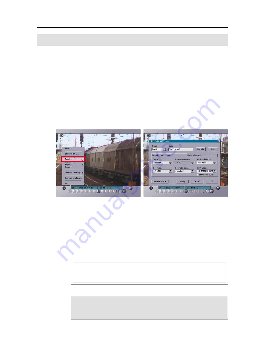
Click the Track menu entry to enter the Track settings dialog box. The
number of configurable tracks is a function of the number of hard disks
installed in the system (see 8.1.1, Creating tracks).

DIS-1/S

Standard 1 HDD

Available tracks = 1

DIS-1/S

Maximum 2 HDD

Available tracks = 2

DIS-1/L

Standard 1 HDD

Available tracks = 1

DIS-1/L

Maximum 4 HDD

Available tracks = 4

8.1.1

Creating tracks

When two or more hard disks are installed, each hard disk is equivalent to
one partition. In OEM state, a single track (track 1) is assigned to all partitions
(hard disks).

If you would like to record only on one track, the following settings
for creating tracks are not necessary.

Attention
All previously recorded pictures will be automatically erased if a
track is reassigned or if several tracks are configured.

Diagram. 8-1

Diagram. 8-2

Summary of Contents for DIS-1/S

Page 1: ...1 Dallmeier electronic GmbH Co KG DK 190 202 GB Rev 3 0 4 040420 Operating manual Installation and configuration Video Streaming Server DIS 1 S DIS 1 L...

Page 2: ...he product or documentation e g printing or clerical errors and where neither intention nor negligence on the part of the manufacturer exists Dallmeier electronic GmbH Co KG Cranachweg 1 D 93051 Regen...

Page 3: ...15 4 3 Set up example 1 16 4 4 Set up example 2 17 5 Starting up for the first time 18 5 1 Login 18 5 2 Main menu 19 6 Basic settings 20 6 1 Selecting the menu language 21 6 2 User interface Player 2...

Page 4: ...1 Permanent 51 8 2 2 Contact 52 8 2 3 Contact with Timer 52 8 2 4 Contact Start Stop 53 8 2 5 IR Start Stop 53 8 2 6 Motion detection 54 8 2 7 Configuring markers for events 56 8 2 8 Recording Off 57...

Page 5: ...function 76 10 2 Exporting to CD 77 10 3 Exporting to DVD 80 11 Import function 81 12 Information menu 83 13 Exiting the main menu 84 14 Shutting down the system 85 Appendix 87 A 1 Contact assignment...

Page 6: ...6 DIS 1 S and DIS 1 L Dallmeier electronic GmbH Co KG...

Page 7: ...duplex variable scalability of picture quality numerous playback functions and integrated image filters for picture quality enhancement make the Video Streaming Server predestined for use in video sec...

Page 8: ...nical features of the DIS 1 S and the DIS 1 L Feature DIS 1 S DIS 1 L Video inputs 1 1 Audio recorder yes yes Control display no yes Hard disks maximum 2 HDD 4 HDD LAN yes yes USB 1 1 2 x 2 x Serial i...

Page 9: ...afe operation of the DIS can only be guaranteed when the housing is closed radio interference suppression and fire protection Only those accessories appliances or upgrading components recommended and...

Page 10: ...l system components are supplied complete with an approved mains cable and mains adapter The appliances should only be connected to earthed safety sockets Wherever possible the DIS should be operated...

Page 11: ...installation and static charging can cause damage to electronic components and result in equipment failure Instructions for the installation of upgrading components Any upgrading components must compl...

Page 12: ...le as options however for special requirements In all cases it is imperative that you pay attention to the safety instructions at the beginning of this manual before you start to instal the device 3 1...

Page 13: ...kit available as an option permits the DIS 1L to be installed in a 19 cabinet Two height modules will be required for installation Fit your system to the 19 support and check that the feet of the devi...

Page 14: ...flap with the ventilation slots can be flipped up Behind it is a replaceable filter pad which should be replaced at regular intervals The 4 LEDs indicate the operating status of the device Error red...

Page 15: ...o IN Y C 6 S Video OUT Y C 7 CVBS IN Composite Video 8 CVBS OUT Composite Video 9 Audio OUT 10 Audio IN 11 USB 1 1 12 Ethernet 13 Power connection 14 Power switch DIS 1 L Please connect up all compone...

Page 16: ...tion of both is also possible The USB mouse can be connected to the USB port at the front of the DIS if you prefer For audio recordings please note that you have to use a line side microphone pre ampl...

Page 17: ...ctronic GmbH Co KG 4 4 Set up example 2 The following example shows the control and evaluation set up for several DIS systems using PView PView Station PView II software on PC or PView Station Etherne...

Page 18: ...case of the DIS 1 L the recording status is also indicated in the display on the front of the unit In the case of the DIS 1 S the green LED for Record flashes to indicate the start of recording 5 1 L...

Page 19: ...de Initially only the buttons Play A and Confi gurations B are active in the menu bar Whether recording is in progress or not you can see at the symbol in the upper left corner of the video picture C...

Page 20: ...ser interface Includes language and transparency Network Network settings such as name and IP address Alarm hosts Forward alarm messages via network to a central computer Interfaces For specifying the...

Page 21: ...h to change the language click on OK Otherwise switch to the Player tab 6 2 User interface Player This tab is for adjusting the settings of the display and the way in which the menu bar is displayed 6...

Page 22: ...full picture to full picture in the Forward single picture playback function see chapter 9 6 2 4 Displaying date and time Tick the checkbox located next to Display date time if the date and time are...

Page 23: ...In the User Interface Player dialog box you can specify if a corresponding audible tone is to be heard in addition to the visible warning message when e g a camera fails by activating the Beep on err...

Page 24: ...3 3 neither the date nor the time can be set manually The date can also be entered directly by means of a calendar function To do this click on the button adjacent to the date display A Select the des...

Page 25: ...this function you must also mark the checkbox for Use time server To be able to work with a Time server you will have to enter settings for the network see Section 7 6 4 Setting the video standard You...

Page 26: ...the DIS to control playback Camera control Click the COM tab Select the Crosslink entry in the Function field The control commands are sent from an external device or an external program to the DIS v...

Page 27: ...te 9600 bits 8 parity keine stop bits 1 The following hex codes are required for control In order to change to playback mode the playback command hex 0x3a first must be sent to the DIS Only at this po...

Page 28: ...xternal control unit The control unit is connected via the external IR interface optional extra on the back side of the DIS or via the built in IR interface on the front side of the DIS between Error...

Page 29: ...failure are recorded in a list The list can be called up via Common settings Event log If you access the DIS menu after such an error has occurred the list automatically appears A corresponding messag...

Page 30: ...ick in the Current password box Enter the old password at the virtual keypad in this example 3 Confirm this entry by clicking on OK Click in the New password box Enter your new password at the virtual...

Page 31: ...in the network contact your authorized network administrator before you adjust the network settings He will be able to advise you about addresses used and free addresses and about the correct setting...

Page 32: ...rm messages Click on Common settings Alarm hosts 7 2 1 Configuring a new alarm host Click on the New button Open the tab Settings Click on the Name field Use the virtual keyboard to enter the name of...

Page 33: ...t for event Contact status Status change of a contact No video signal Camera failure problematic line or similar Hard disk error failure Defective hard disk Track deleted The recording track has been...

Page 34: ...eo recording In the Alarm hosts list select the host for which you would like to set the calendar A Click on the Scheduler button B All areas in the weekly plan which are shown as light colored are ac...

Page 35: ...on on the current marking Mark larger time areas Click the beginning of the desired time area with the right mouse button and hold By moving the mouse you now can lasso the inactive area to mark it Yo...

Page 36: ...kly plan Open the tab Exceptions Click on New Mark the day for which you would like to apply the deviation setting in the displayed calendar Confirm your selection by clicking on OK After confirming t...

Page 37: ...If you want the set exception to apply to other days as well you can copy these settings for a new date Click on Copy Select the new date in the displayed calendar Confirm the selection by clicking o...

Page 38: ...larm host In the Alarm hosts list select the alarm host whose settings you would like to copy Click on Copy The name of the copied alarm host now appears in the Alarm hosts list and in the Name field...

Page 39: ...host In the Alarm hosts list mark the alarm host for which you wish to activate or deactivate the settings activate mark the checkbox active deactivate do not mark the checkbox active The settings for...

Page 40: ...the Decoder for SeMSy available rights allocation you can read coded image data from another DIS into the respective DIS and decode them via the management system The following block diagram shows th...

Page 41: ...ecoded for viewing on a monitor At this receiving DIS Decoder for SeMSy available must be activated in the SeMSy configuration as this otherwise will reject access to the decoder If a DIS is to transm...

Page 42: ...icasting is that messages can be sent to multiple participants or closed participant groups at the same time A general distinction is made between three connection types Point to point connection Here...

Page 43: ...mation makes it easier for the client to synchronize the data packets Even if the DIS records sound to accompany the picture the audio signal is not sent to the network in this mode RTP implementation...

Page 44: ...client In order to receive DIS video streams from a DIS configured as a server you will need to set your DIS to act as a client To do this click the Client tab Mode Here you can set the mode with whi...

Page 45: ...id protocol and changed as needed The list of configured servers is stored on the DIS and remains intact after a reboot Refer to the Server tab DaVid to see which servers are stored If changes were ma...

Page 46: ...Available tracks 2 DIS 1 L Standard 1 HDD Available tracks 1 DIS 1 L Maximum 4 HDD Available tracks 4 8 1 1 Creating tracks When two or more hard disks are installed each hard disk is equivalent to on...

Page 47: ...k the corresponding checkbox e g for partition 1 and undo the mark for partition 2 if necessary Click the Name field and enter the desired track designation using the virtual keyboard Click Apply Clic...

Page 48: ...e recording A low bit rate stands for a high degree of compression with a relatively small volume of data but poor picture quality A high bit rate stands for a low degree of compression with a relativ...

Page 49: ...possible with 25 pictures per second Audio bit rate The audio bit rate setting allows you not only to control the audio quality but also the amount of required hard disk space to a certain extent The...

Page 50: ...ng recordings a message is issued before the change is adopted warning you that all the pictures recorded on this track will be deleted Your changes are not adopted until you answer this safety prompt...

Page 51: ...A The Recording settings dialog box will open In the Track B field select the track whose recording mode you would like to set Select the desired mode of recording in the Mode C field 8 2 1 Permanent...

Page 52: ...ntact used is an Opener idle state contact closed please mark the checkbox Invert signal B 8 2 3 Contact with Timer When Contact with timer is set recording is triggered in the same way as under the C...

Page 53: ...then runs when the contact is pressed and stops again when you release the contact Settings Open the tab Contact start stop In the Start contact box select the contact for starting recording In the St...

Page 54: ...pen the tab motion detection Mark the active checkbox To set the threshold value and timeout please refer to the following explanations Setting the threshold value The threshold value specifies how mu...

Page 55: ...recording duration after an event has exceeded the set threshold value and prompted a recording If the timeout is set to 10 seconds for example and only one triggering event occurs recording is stoppe...

Page 56: ...d again off With Motion event recording a marker is set for each motion event If the checkbox for Recording start is marked a marker will be recorded regardless of other settings each time a recording...

Page 57: ...has been set it is easier to locate the section in question using the picture searching function To make use of this function click the checkbox next to Set marker 8 2 8 Recording Off Setting the rec...

Page 58: ...s opens the Scheduler dialog box In the Track box select the track for your setting A In the weekly plan you can stipulate the times at which recordings with a particular recording mode are to be made...

Page 59: ...been marked with the recording mode Contact The smallest time period that can be set is 15 minutes Setting a larger time area Click the desired recording mode button e g Motion Click with the left mo...

Page 60: ...y plan with the not active function There are two different ways of deactivating recording for a specified time period 1 Click on the not active button and then specify the time period in the way desc...

Page 61: ...can be stipulated as exceptions in the weekly plan Open the tab Exceptions Click on the New button In the Calendar which opens mark the day for which you wish to make an exception Confirm your selecti...

Page 62: ...00 hours and 15 00 to 24 00 hours and the Contact Start Stop recording mode for 7 00 to 15 00 hours Click on OK to have this exception taken into account in the weekly plan Copying an exception settin...

Page 63: ...g an exception setting Mark the date concerned in the list Click on the Delete button The settings in the weekly plan will only be implemented if the Scheduler is active in the Mode box in the Recordi...

Page 64: ...own on the monitor that will be changed by new settings The changes can be viewed immediately on the screen To obtain a better impression of the overall picture while making a particular setting you c...

Page 65: ...he picture Focus Accentuation of edges between areas of different brightness Color Color tone setting specially for NTSC Clicking once on the Standard button will restore all settings to their standar...

Page 66: ...tion the noise filter automatically adapts to the existing state of the input signal dynamic The static value setting does not affect the dynamic noise filter Click on the Standard button to automatic...

Page 67: ...the system was previously configured To enter the main menu and access the playback functions click on the left mouse button and enter your password at the virtual keypad default 3 In the top left cor...

Page 68: ...nd frame by frame Reverse playback with one frame per click 5 Rewind Reverse playback at normal speed 6 Stop All playback functions are deactivated except the play button The recorder is again in live...

Page 69: ...e could assume that they are in live mode Configured settings then could be accessed without any trouble at all The date and time have been programmed to appear differently in order to determine if yo...

Page 70: ...mouse button kept pressed you can move quickly through the picture sequence to a specific point of the recording Click once again on the Controller On Off button C to fade out the slide controller Ch...

Page 71: ...ller Diagram 9 12 B Now only a specific area of the track will be scanned not the entire track When the quick search sliding bar is positioned between both end points first picture last picture these...

Page 72: ...pen the tab Events The list shows the events that have occurred Please note that only those events are listed which were selected in the Event recording menu see chapter 8 1 7 Click twice on a listed...

Page 73: ...vals You can also search for specific pictures by moving backwards and forwards through your recording in defined steps Steps can be taken in Days Hours Minutes Seconds The size of the step is set in...

Page 74: ...9 When you release the mouse button the area inside the square is displayed in enlarged format Diagram 9 20 In the schematic display in the lower right corner of the screen the position of the traced...

Page 75: ...the section Move the cursor to the small display area of the zoom window Click with the left mouse button and keep it depressed You now can move the position of the section within the small window 9...

Page 76: ...done the 5 GB of memory reserved for the image file can be accessed for recording Click Export Settings Remove the mark in the checkbox next to Export available The export function now is suppressed a...

Page 77: ...start and stop points of the picture sequence to be exported are set by the start and stop entries To define the start point of the picture se quence click on the button Diagram 10 4 B next to the dat...

Page 78: ...n not over a button or a display field when doing this To undo the transparent setting click once again using the right mouse button You can check the number of pictures and the storage space required...

Page 79: ...ten to a closed CD Click on Start to start writing Do you want to write more picture sequences to CD When writing has been completed click on the Back button Enter the data date start and stop for the...

Page 80: ...dialog box click OK Exiting the export function Click on Close to exit the Export dialog box 10 3 Exporting to DVD The settings and procedure to be followed are identical to those described in section...

Page 81: ...al drive Connect the external CD ROM drive to your DIS via the USB interface and insert a CD ROM with archived picture sequences see chapt 10 Export function The CD ROM drive is automatically detected...

Page 82: ...will indicate to you that the pictures being played back are pictures that have already been exported To return to the select menu for Import click on the Stop button In order to see the content of a...

Page 83: ...nder About Click on About In the pop up menu you will find details of your recorder e g recorder model serial number and version of the installed software Click on the Extended button for information...

Page 84: ...with the playback functions will also be phased out when you click on Exit You are now in Record mode Attention If you had previously selected Off in the setting Record Record settings Mode there wil...

Page 85: ...tting down the system To switch off your DIS click first on System shut down If you answer the security prompt with Yes you will be able to disconnect your system from the power supply after approxima...

Page 86: ...86 DIS 1 S and DIS 1 L Dallmeier electronic GmbH Co KG...

Page 87: ...87 Dallmeier electronic GmbH Co KG Appendix...

Page 88: ...ed to the PINs 2 to 5 PIN 1 2 3 4 5 6 External contacts for recording control A 2 Memory requirement e t a r t i B s p b M B G n i t n e m e r i u q e r y r o m e M s p f 5 2 e t a r e m a r F y a d 1...

Page 89: ...constant variable 500 Kbit s 2 Mbit s MPEG 1 1 Mbit s 16 Mbit s MPEG 2 Network protocols RTP UDP TCP FTP IP RTCP SNMP HTTP IGMP ICMP ARP DHCP Unicast Multicast Video standards MPEG 1 ISO IEC 11172 2 M...

Page 90: ...to 2 x chinch connectors Alarm inputs 4 x alarm contacts isolated inputs through VAGO terminal strip Serial DIS 1 S and DIS 1 L 1 x RS 232 9 pin D SUB IR remote control Multiprotocol compatible USB 2...

Page 91: ...ower input DIS 1 S and DIS 1 L approx 28 W Temperature 0 to 50 C Humidity 5 95 Weight max 8 kg Case height DIS 1 S 1 HU DIS 1 L 2 HU Dimensions DIS 1 S B 425 x H 43 x T 350 mm With case feet H 51 mm D...

Page 92: ...150 dpi dots per inch would require approximately 3 MB of memory Various com pression methods are used to reduce the volume of data To obtain a general idea of how this works let s consider the JPEG...

Page 93: ...PEG compression technique is suitable for single pictures but not for video sequences An adaptation of the JPEG compression method for video sequences is available under the name M JPEG Data compressi...

Page 94: ...ontaining a change from the preceding I frame This severely reduced picture is called a P frame P stands for Predicted Severe distortions in a picture s contents may arise when there is only one P fra...

Page 95: ...appens for example when switching over from one camera to another it is impossible to compare the last frame of camera 1 with the first frame of camera 2 consequently it is recommended to refrain from...

Page 96: ...half pictures Resolution 352 x 288 SIF Data rate 1 2 to 3 MBit s MPEG 2 ISO 13818 25 frames 50 fields In the interlacing method frame full picture field half picture Supports Dolby Surround Resolutio...

Page 97: ...wing EC Directives Elektromagnetische Vertr glichkeit 89 336 EWG electromagnetic compatibility Niederspannung 73 23 EWG low voltage Folgende Normen wurden angewandt The following specifications were a...

Reviews: