background image

Test and Remove Modules

10

5  Test and Remove Modules

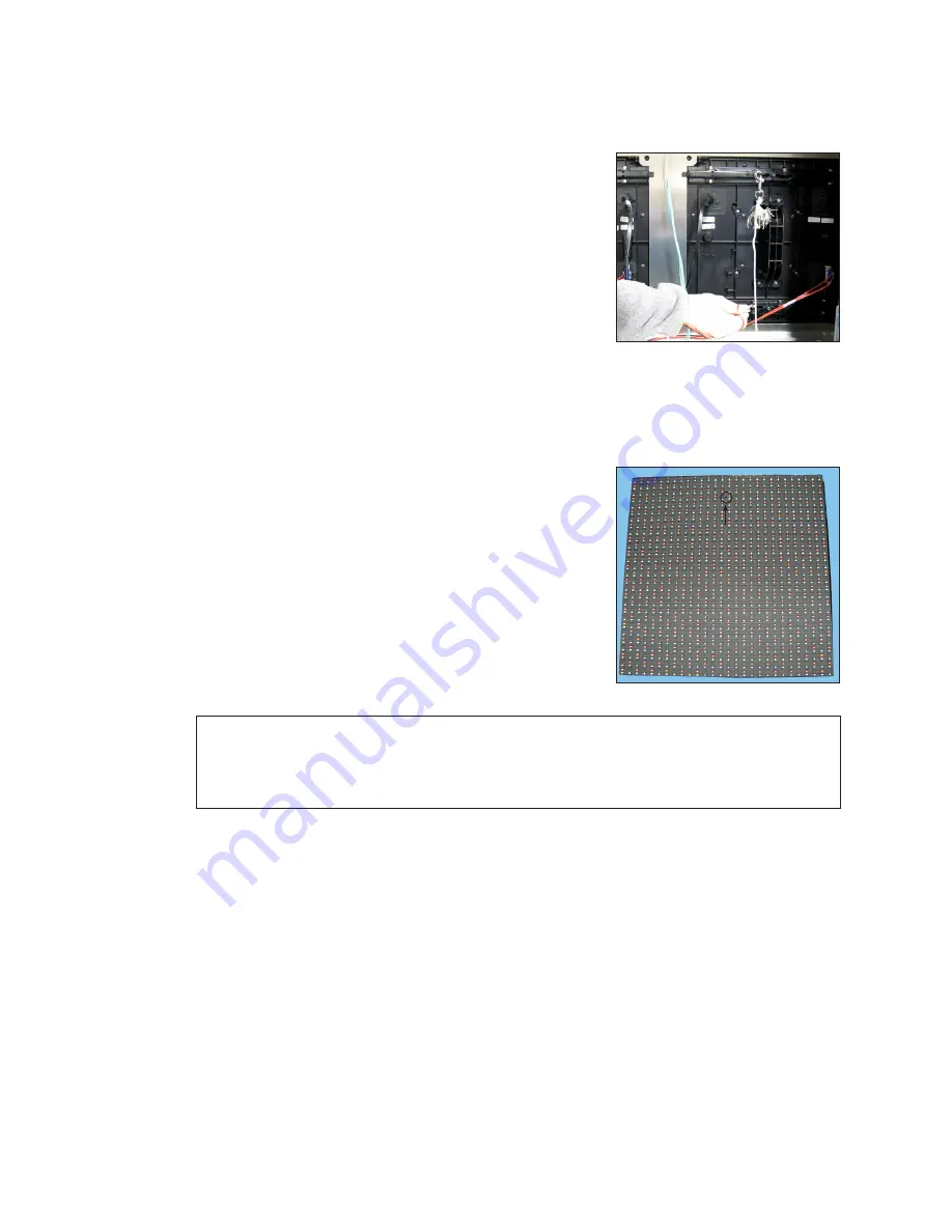
Module Lanyard Attachment

Attach a module lanyard (located in the spare parts 

rack) whenever removing a module. To attach a module 

lanyard, follow these steps: 

1� 

Attach one end of the lanyard to an attachment ring 

on the top of the of the module. Refer to 

Figure 11

.

2� 

Feed the lanyard over a wire rod or through a nearby 

upright. Do not anchor the module to another 

module.

3� 

Attach the other end of the lanyard to the 

attachment ring on the top of the module.

Remove a Module (Front Access)

Required Tools:

 1/8" hex head wrench, module lanyard (from the spare parts rack)

1� 

Insert the 1/8" hex head wrench into the top access 

hole. Refer to 

Figure 12

.

2� 

Turn the latch release approximately a quarter-

turn counterclockwise. You should feel the module 

release from the display face.

3� 

Pull the module from the display face just far enough 

to reach the back of the module.

4� 

Disconnect the power and SATA cables from the 

back of the module.

5� 

Gently place the module on a clean and dry surface.

Note: 

If there is no place to set the module, use a safety lanyard to hang the 

module from the rear of the display. Attach the safety lanyard in a way that 

takes up slack on the lanyard. Carefully let the module hang while ensuring it 

does not damage the LEDs, louvers, or gasket.

Reinstall the Module (Front Access)

When installing new modules, place them in the outer ring of the display.

1� 

Reinstall the module by aligning it with the opening.

2� 

Reattach the power and SATA cables.

3� 

Carefully hook the module into the module sheet and rotate the module top to the 

module sheet. Verify that SATA and power cables are not being pinched between 

the module and display face.

4� 

Firmly press the upper half of the module against the display face.

5� 

Insert the 1/8" hex head wrench into the bottom access hole and turn approximately 

a quarter-turn clockwise or until you feel it latch in place.

Figure 11: 

Attach Safety Lanyard 

to Modules

Access

Hole

Figure 12: 

Module Access Hole

Summary of Contents for BLD Series

Page 1: ...201 Daktronics Drive Brookings SD 57006 5128 www daktronics com support 800 325 8766 BLD SERIES DIGITAL BILLBOARD SERVICE MANUAL P2053 DD4245363 Rev 03 07 March 2022...

Page 2: ...he limits for a Class A digital device pursuant to part 15 of the FCC Rules These limits are designed to provide reasonable protection against harmful interference when the equipment is operated in a...

Page 3: ...e Modules 10 Module Lanyard Attachment 10 Remove a Module Front Access 10 Reinstall the Module Front Access 10 Remove a Module Rear Access 11 Remove Fan Plenum 11 Remove a Module from Behind an ISP En...

Page 4: ...oot Bar 20 Replace the SmartLinkTM Optional 21 Replace the Heater 21 8 Test and Replace the Multi Direction Light Sensor 22 Test the MDLS 22 Replace the MDLS 22 9 Access and Troubleshoot the Webcam 23...

Page 5: ...ase 60 HZ Amps L1 L2 Total Watts Spare Parts Every Daktronics digital billboard is shipped with spare parts that include commonly replaced components The table lists some of the components that may be...

Page 6: ...ntake Ventilation Exhaust Doors Spare Parts Support Ledger Figure 3 Spare Parts Rack in Display 4 Lift the rack upward and outward to remove it from the display enclosure Remove a Module From Spare Pa...

Page 7: ...ontact the ASM to order components when needed Display FRUs Control System FRUs ProLink Router Temperature Sensor Line Filter VIP 5160 2 Power Supply Light Sensor MDLS Module Ethernet Switch Axial Fan...

Page 8: ...ayout drawing for display specific power distribution Display Signal Overview Refer to DWG 4118208 and DWG 4118209 for display specific signal routing Signal is sent from the DMP 8000 to the VIP 5160...

Page 9: ...eshoot the Display Work with Daktronics help desk or experienced technicians to address display issues Refer to the following table for troubleshooting steps Issue Issue Image Troubleshooting Steps En...

Page 10: ...l drawing If not correct the signal path Display too bright 1 Immediately call Daktronics help desk and have them blank the display 2 Verify the Multi Direction Light Sensor MDLS is connected 3 Inspec...

Page 11: ...nctioning Disconnect and reconnect power to the PLR 6 Verify there is power to that display section by checking module status indicators on multiple modules If there is no power check the power entran...

Page 12: ...le power indicator is on there is most likely a SATA cable issue If the module power indicator light is off check the power supplies for the modules at each end of the issue are on If not power or sig...

Page 13: ...corner of the door outward so it clears the tab located on the display back sheet Refer to Figure 9 3 Lift the door upward to disengage its tabs from the slots on the display s back sheet Refer to Fig...

Page 14: ...f the module 4 Disconnect the power and SATA cables from the back of the module 5 Gently place the module on a clean and dry surface Note If there is no place to set the module use a safety lanyard to...

Page 15: ...roximately a quarter turn clockwise to disengage the latch 6 With a 1 8 hex head wrench turn the top latch gear approximately a quarter turn clockwise to disengage the latch Note Maintain a firm grip...

Page 16: ...losure allow it to slowly rotate open and out of the way 3 If needed remove all the pins from the other side of the SmartLinkTM carefully lift the SmartLinkTM out of the enclosure and set aside while...

Page 17: ...rd rings or the lanyard to pull the module firmly against the face sheet 6 With a 1 8 hex head wrench turn the top latch gear approximately a quarter turn counterclockwise to engage the latch 7 Connec...

Page 18: ...t the self test 4 Verify the module is running a self test Remove the SATA cable and cycle power to the module to stop the self test For more information refer to Performing a Daktronics Digital Billb...

Page 19: ...les change colors it shows they all work and that visually the display is fine but there could still be a signal failure that will not show up visually because of redundancy The Amber Yellow and Magen...

Page 20: ...Disconnect the power supply from any wiring harnesses connected to it 2 Push down on the top leg of the wire form bracket and rotate the power supply clockwise Refer to Figure 27 3 Carefully pull the...

Page 21: ...ISP enclosure by opening the rear access door with the control equipment label 2 Use a Phillips screwdriver to loosen the four screws that hold the cover onto the ISP enclosure Refer to Figure 29 or...

Page 22: ...of the unit Refer to Figure 33 iBoot Bar The iBoot Bar located behind the VIP 5160 performs power loss detection and remote power cycling Some customers may use an optional SmartLinkTM instead of an i...

Page 23: ...the network communication cable 4 Loosen the screws holding the DMP 8000 bracket to the control enclosure 5 Slide the DMP 8000 and bracket so that the screws can go through the keyholes and then caref...

Page 24: ...re 4 Reverse Steps 1 3 to install the new router 5 Ensure all cables are installed in the same ports as on the previous router Replace the Ethernet Switch 1 Disconnect the power cable from the Etherne...

Page 25: ...four screws that secure the SmartLinkTM to the mounting plate 7 Reverse Steps 1 6 to install the new SmartLinkTM 8 Call Daktronics help desk and provide them with the new MEID number circled in Figur...

Page 26: ...splay should dim within a couple of minutes Remove the fabric and verify the display returns to the brighter setting If possible work with the help desk and have them monitor the display IDM dimming l...

Page 27: ...am is not functioning properly Refer to the table below Issue Troubleshooting Steps All LED indicators on the webcam are off Check Cat5e connections inside surge protector to ensure they are secure Ve...

Page 28: ...osure Inspect the control system for damage Perform an inventory of the spare parts rack Have the help desk run a diagnostics check of the display Work with the help desk to repair any issues found du...

Page 29: ...splays a pixel is the smallest block of light emitting devices that can generate all available colors Power supply a display component that converts incoming AC line voltage to low DC voltage In the B...

Page 30: ...This page intentionally left blank...

Page 31: ...se listed in this section Reference Drawings Block Diagram BLD 0100 SATA Routing 4 6 High DWG 4118208 Block Diagram BLD 0100 SATA Routing 7 8 High DWG 4118209 Reference Documents ProLink Router 6X5X I...

Page 32: ...This page intentionally left blank...

Page 33: ...Daktronics Warranty and Limitation of Liability 29 B Daktronics Warranty and Limitation of Liability Click here to view the Daktronics Warranty Limitation of Liability statement SL 02374...

Page 34: ...This page intentionally left blank...

Reviews: