370 S 370 S L 370 PP 370 PP L
7
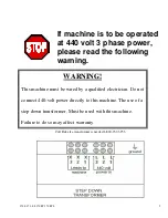
16 amp service is recommended. Machines are rated at +/-10%. The wires are connected to the terminal block inside the control
cabinet.
WARNING!!!!!
All electrical connections should only be made by a qualified electrician. Before turning on power,
check that all electrical components are in place. They may have come loose in shipping. If you have
any questions please call Dake or consult your electrician.
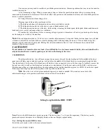
D: Locate the air regulator on the rear of the vertical column. With a quick disconnect or hard plumb air to the
regulator. It is recommended to have an emergency air shut off valve. Once all the fittings are secure, turn the air supply on to
the machine. The gauge should read at 90 PSI. If the reading is more or less adjust the regulator to 90 PSI.
Incoming air
from the air compressor must be clean and dry. Use all precautions and water traps as necessary.
E: If loading or unloading tables were ordered install them now. Make sure the tables are level and in precise
alignment with the feeder unit.
WARNING!!!!!
Failure to align tables and level to the correct height of the feeder may cause material to roll or
catch on other components.
Continuation of the set up is on page 9.
INSTALLATION OF THE BLADE
WARNING!!!!!
Before performing the following operations, the electrical supply must be LOCKED OUT.
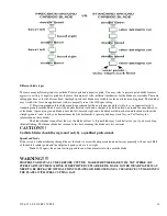
Installing the blade (Ferrous head)
Open the Plexiglas cover. Open the magnetically latched blade guard. Remove the spindle flange bolt using the socket wrench
provided with the saw. (Standard threads) Remove the blade flange, and wipe the blade surface of the flange and spindle clean.
Carefully slide the blade up through the coolant distribution tubes. Take care not to bend these tubes. With a rolling motion of
the blade counter clockwise, push against the chip brush and slide blade over the spindle shoulder. Rotate the blade on the
shoulder to align the two large drive pin holes. Insert the flange pins through the drive pin holes and insert bolt, finger tighten at
this point.
The back lash must be removed from the blade.
This is done by pushing the blade against rotation, until it
bottoms out on the drive pins. (Push Downward) While holding the blade against the pins tighten the spindle bolt securely.
Failure to remove the back lash may result in blade breakage and personal injury!
BLADE INSTALLATION
A: Clean spindle and flange faces, so there are no chips on the faces.
B: Install blade on the spindle shaft shoulder, so the teeth are facing down, for clockwise rotation, and install blade
flange. Take care that you do not hit any machine parts with the carbide tips; this may affect the blade performance.
C: Screw the spindle bolt in finger tight
D: Holding the spindle shaft with the wrench tighten bolt securely.
E: Close blade cover.
Continued on page 11
Summary of Contents for Euromatic 370 PP
Page 9: ...370 S 370 S L 370 PP 370 PP L 9 ...
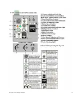
Page 10: ...370 S 370 S L 370 PP 370 PP L 10 Actual control panel layout may vari ...
Page 32: ...370 S 370 S L 370 PP 370 PP L 32 ...
Page 33: ...370 S 370 S L 370 PP 370 PP L 33 ...
Page 38: ...ALIMENTAZIONE 230V 60Hz 230V 60Hz POWER SUPPLY POWER SUPPLY ...
Page 39: ...HL4 ILLUMINAZIONE LAMA POWER SUPPLY ...
Page 40: ...LAMPEGGIATORE LAMA IN MOTO 24VAC MORSA 24VAC EMERGENCIES ...
Page 44: ...9 11 2 4 5 10 3 6 7 8 1 CH1 LC4HR424ACJ KA5 RITORNO CARRO COUNTER ...
Page 45: ...TERMINAL ...
Page 49: ...10 2 2019 Euromatic 370 2 Head Cylinder Unit Ref 005 ...
Page 51: ...10 2 2019 Euromatic 370 4 Bedplate Unit Ref 008 ...
Page 53: ...10 2 2019 Euromatic 370 6 Head Unit Ref 002 ...
Page 55: ...10 2 2019 Euromatic 370 8 Vise Unit Ref 004 ...
Page 57: ...10 2 2019 Euromatic 370 10 Group Feeder P R ...
Page 59: ...10 2 2019 Euromatic 370 12 Group Alimentador P P Ref 014b Alimentador Ref 014b ...


