Page
3
of
62
SK2014
‐
SON
‐
002
‐
TechMnl
‐
FMCD
‐
003
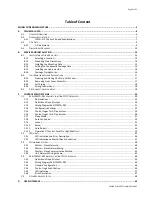
Table
of
Content
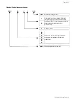
MODEL
CODE
NOMENCLATURE
..........................................................................................................................................
5
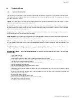
A.
TECHNICAL
DATA
......................................................................................................................................................
6
A.1.
G
ENERAL
D
ESCRIPTION
......................................................................................................................................................6
A.2.
G
ENERAL
S
PECIFICATION
....................................................................................................................................................7
A.2.1.
FMCD–V–EC
Series
3
‐
Speed
Specifications
........................................................................................................7
A.3.
C
OIL
D
ATA
......................................................................................................................................................................9
A.3.1.
2
‐
Pipe
Systems
...................................................................................................................................................9
A.4.
D
IMENSIONAL
D
RAWINGS
...............................................................................................................................................
10
B.
SERVICE
AND
INSTALLATION
...................................................................................................................................
13
B.1.
I
NSTALLATION
OF
H
IGH
‐
W
ALL
U
NIT
..................................................................................................................................
13
B.1.1.
Selecting
a
Location
........................................................................................................................................
13
B.1.2.
Mounting
Plate
Dimensions
............................................................................................................................
14
B.1.3.
Installing
the
Mounting
Plate
.........................................................................................................................
15
B.1.4.
Drilling
the
Condensate
Drainage
Hole
...........................................................................................................
15
B.1.5.
Installing
the
Hydronic
Unit
............................................................................................................................
16
B.1.6.
Drainage
Piping
Works
....................................................................................................................................
16
B.2.
U
NIT
M
AINTENANCES
AND
P
REPARATIONS
.........................................................................................................................
17
B.2.1.
Opening
and
Closing
Of
Lift
‐
Up
Grille
Cover
...................................................................................................
17
B.2.2.
Removing
Front
Cover
Assembly
....................................................................................................................
17
B.2.3.
Air
Purging
......................................................................................................................................................
18
B.2.4.
Wiring
Connections.........................................................................................................................................
18
B.3.
P
IPE
C
ONNECTIONS
WITH
V
ALVE
......................................................................................................................................
19
C.
CONTROL
SPECIFICATIONS
......................................................................................................................................
20
C.1.
SK
‐
NCFMCD
‐
001
C
OMPLETE
FUNCTION
FCU
C
ONTROLLER
................................................................................................
20
C.1.1.
Abbreviations
..................................................................................................................................................
20
C.1.2.
Definition
of
Input/Output
.............................................................................................................................
20
C.1.3.
Wiring
Diagram
SK
‐
NCFMCD
‐
001
...................................................................................................................
21
C.1.4.
Configuration
Settings
....................................................................................................................................
22
C.1.5.
Control
Logics
for
2
‐
Pipe
System
....................................................................................................................
24
C.1.6.
Control
Logics
for
4
‐
Pipe
System
....................................................................................................................
28
C.1.7.
Sleep
Mode
.....................................................................................................................................................
31
C.1.8.
Auto
Fan
Speed
...............................................................................................................................................
32
C.1.9.
Louver
.............................................................................................................................................................
33
C.1.10.
Buzzer
.............................................................................................................................................................
33
C.1.11.
Auto
Restart
....................................................................................................................................................
33
C.1.12.
Operation
Of
Control
Panel
On
High
‐
Wall
Unit
..............................................................................................
34
C.2.
LED
L
IGHTS
.................................................................................................................................................................
35
C.2.1.
LED
Indication
and
Error
Description
..............................................................................................................
36
C.2.2.
LED
Indication
on
Master/Slave
Connection
..................................................................................................
37
C.3.
N
ETWORKING
S
YSTEM
...................................................................................................................................................
38
C.3.1.
Master
–
Slave
Network..................................................................................................................................
38
C.3.2.
Master
–
Slave
Network
Setup
.......................................................................................................................
39
C.3.3.
Master
–
Slave
Communication
Method
........................................................................................................
42
C.3.4.
Unit
Network
Wiring
Scheme
.........................................................................................................................
43
C.4.
SK
‐
NCFMCD
‐
002
L
IMITED
FUNCTION
FCU
C
ONTROLLER
...................................................................................................
44
C.4.1.
Definition
of
Input/Output
.............................................................................................................................
44
C.4.2.
Wiring
Diagram
SK
‐
NCFMCD
‐
002
...................................................................................................................
45
C.4.3.
Onboard
Configuration
...................................................................................................................................
46
C.4.4.
Control
Logic
Specification..............................................................................................................................
46
C.4.5.
LED
Indication
.................................................................................................................................................
47
C.4.6.
Error
Description
.............................................................................................................................................
47
C.5.
O
PEN
M
ODBUS
PROTOCOL
.............................................................................................................................................
48
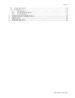
D.
USER
INTERFACE
.....................................................................................................................................................
52
Summary of Contents for FMCD*ECM series
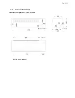
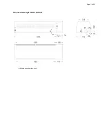
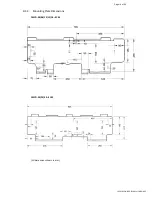
Page 11: ...Page 11 of 62 Dimensional drawing for FMCD 20 24 ECM All dimensionsshown in mm ...
Page 21: ...Page 21 of 62 SK2014 SON 002 TechMnl FMCD 003 C 1 3 Wiring Diagram SK NCFMCD 001 ...
Page 45: ...Page 45 of 62 SK2014 SON 002 TechMnl FMCD 003 C 4 2 Wiring Diagram SK NCFMCD 002 ...
Page 62: ...Page 62 of 62 SK2014 SON 002 TechMnl FMCD 003 ...


