


30
Commissioning and Operation
Items to be Confirmed Before Turning on Unit
■ Ensure that the water pump and the unit are connected.
Use the PCB controller to Control the on and off the water pump using the water pump output on the PCB
controller; otherwise the BPHE may burst due to freezing.
The water pump connection point must have no voltage. If a voltage circuit is connected, basic components may
be damaged.
■ Power on the unit to preheat the crankcase for at least 12 hours before starting up the unit for the first time or
after a long-term stoppage. This ensures that the compressor works properly.
■ Before turning on the unit, check that the water pump is filled with water.
Before turning on the water pump, open the water supply valve, fill the pump with water, and discharge free air
in the system
■ Wiring of the unit: Check that the diameter of the wires meets requirements; the wires are correctly connected;
the grounding line is securely connected;
■ Before turning on the unit, clean the water system and ensure that pipes are clean without contaminants.
■ Make sure that the working conditions do not exceed the rated working range.
Items to be Checked during the Pilot Run
Check the following items after the unit has worked properly for a period of time:
S/N
Item
Checking Method
Reference Standard
1
Power supply voltage
Voltage
Rated voltage±10%
2
Working current of a single compressor
Current
13 - 23A
3
Working current of a single fan
Current
2 - 5A
4
Inlet water temperature in cooling operation
Temperature
15- 20°C
5
Outlet water temperature in cooling operation
Temperature
6 -15°C
6
Inlet/outlet water temperature difference
Temperature
2 - 7°C
7
Discharge air temperature of the compressor
Temperature
65 -115°C
8
Low pressure in cooling mode
Pressure
6.5 - 10.0bar
9
High pressure in cooling mode
Pressure
22 - 41.5bar
10
Vibration and operation noise
Listen or touch
No abnormal vibration or noise
NOTE: THE REFERENCE STANDARDS ARE USED TO CHECK WHETHER A UNIT WORKS PROPERLY ONSITE. REFERENCE
STANDARDS ARE DETERMINED BASED ON THE MAXIMUM AND MINIMUM WORKING CONDITIONS. IF REFERENCE STANDARDS ARE
EXCEEDS AFTER THE UNIT HAS PROPERLY WORKED FOR A PERIOD OF TIME, CONTACT THE LOCAL DEALER OR DAIKIN FOR HELP.
Note: Before the pilot run, check that the
following conditions are met and read
the "Safety Precautions" again.
Summary of Contents for UAL-A Series
Page 8: ...7 Dimensions Unit mm WATER IN WATER OUT UAL WATER IN WATER OUT UAL UAL ...
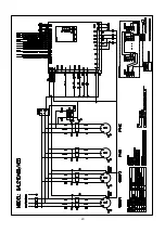
Page 14: ...13 Wiring Diagrams 208 230V 3Ph 60Hz ...
Page 15: ...14 ...
Page 16: ...15 ...
Page 17: ...16 460V 3Ph 60Hz ...
Page 18: ...17 ...
Page 19: ...18 380V 3Ph 60Hz ...
Page 20: ...19 ...
Page 21: ...20 ...
Page 38: ...37 220V 1Ph 60Hz Wired Controller Instruction Dimensions Controller Installation ...


