


27
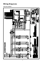
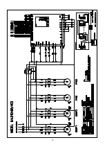
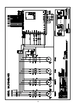
Hydraulic Calculation and Pipe System
Pipe design for the air-conditioning system
■ The pipes of an air conditioning system must have sufficient transportation capacities. For example, the water
system must ensure that the water flowing through the air conditioning unit or fan coil reaches the rated flow rate
to ensure that the unit works properly.
■ Deploy pipes properly. Use pipes with reverse return if possible. Although the initial investment is increased
a little, the water flow in the system is more stable. If pipes have no reverse return design, pressure between
branch pipes must be balanced in the design process.
■ When determining the diameters of pipes, ensure that the transportation capacity is sufficient, the resistance
and noise is minimal, and that the unit works economically. A larger pipe diameter requires more investment,
but the flow resistance is smaller, the circulation pump consumes less energy, and the operation cost is smaller.
Therefore, a balance needs to be achieved between the operation cost and investment by designing the pipe
diameter properly. Avoid a large water flow with small temperature variation to ensure that the pipe system is
economical.
■ In the design process, calculate water resistance accurately to ensure that water pressures between circuits are
well balanced and that the air conditioning system works with the best water and thermal conditions.
■ The pipe system of an air conditioning system must meet the adjustment requirements for partial workload.
■ The pipe system of an air conditioning system should use energy saving technologies whenever possible.
■ Pipes and accessories of the pipe system must meet the related requirements.
■ The design of the pipe system must facilitate maintenance, operation, and adjustment.
* Determining the diameter of pipes in the air conditioning system
The pipe diameter is determined based on the following:
The water speed should be determined by the recommendations in the first table and design the water pipe
diameters accordingly, or you can determine the water pipe diameter based on water flow in the second table.
Table 1: Recommended water speed (m/s)
Diameter (mm)
12
20
25
32
40
50
65
80
Closed water system
0.4 - 0.5
0.5 - 0.6
0.6 - 0.7
0.7 - 0.9
0.8 - 1.0
0.9 - 1.2
1.1 - 1.4
1.2 - 1.6
Open water system
0.3 - 0.4
0.4 - 0.5
0.5 - 0.6
0.6 - 0.8
0.7 - 0.9
0.9 - 1.0
0.9 - 1.2
1.1 - 1.4
Diameter (mm)
100
125
150
200
250
300
350
400
Closed water system
1.3 - 1.8
1.5 - 2.0
1.6 - 2.2
1.8 - 2.5
1.8 - 2.6
1.9 - 2.9
1.6 - 2.5
1.8 - 2.6
Open water system
1.2 - 1.6
1.4 - 1.8
1.5 - 2.0
1.6 - 2.3
1.7 - 2.4
1.7 - 2.4
1.6 - 2.1
1.8 - 2.3
Table 2: Pipe diameter and resistance loss in unit length
Diameter of the
steel tube (mm)
Closed water system
Open water system
Water flow (m
3
/h)
kPa/100m
Water flow (m
3
/h)
kPa/100m
15
0 - 0.5
0 - 60
--
--
20
0.5 - 1.0
10 - 60
--
--
25
1.0 - 2.0
10 - 60
0 - 1.3
0 - 43
32
2.0 - 4.0
10 - 60
1.3 - 2.0
11 - 40
40
4.0 - 6.0
10 - 60
2.0 - 4.0
10 - 40
50
6.0 -11.0
10 - 60
4.0 - 8.0
--
65
11.0 -18.0
10 - 60
8.0 -14.0
--
d
=
4m
w
3.14 v
In the formula: m
w
-------water flow m
3
/s
v---------water speed m/s
Summary of Contents for UAL-A Series
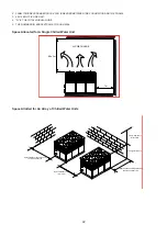
Page 8: ...7 Dimensions Unit mm WATER IN WATER OUT UAL WATER IN WATER OUT UAL UAL ...
Page 14: ...13 Wiring Diagrams 208 230V 3Ph 60Hz ...
Page 15: ...14 ...
Page 16: ...15 ...
Page 17: ...16 460V 3Ph 60Hz ...
Page 18: ...17 ...
Page 19: ...18 380V 3Ph 60Hz ...
Page 20: ...19 ...
Page 21: ...20 ...
Page 38: ...37 220V 1Ph 60Hz Wired Controller Instruction Dimensions Controller Installation ...


