


7
English
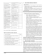
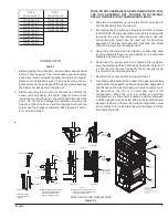
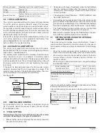
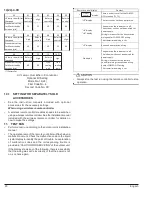
DFK -B
Downfl ow Ki t
DFK-C
Downfl ow Ki t
FTQ 1 8 TAVJUA
FTQ 4 2 TAVJUA
FTQ 1 8 TAVJUD
FTQ 4 2 TAVJUD
FTQ 2 4 TAVJUA
FTQ 4 8 TAVJUA
FTQ 2 4 TAVJUD
FTQ 4 8 TAVJUD
FTQ 3 0 TAVJUA
FTQ 3 0 TAVJUD
FTQ 3 6 TAVJUA
FTQ 3 6 TAVJUD
DOWNFLOW KIT
Table 1
1.
Before flipping the air handler, remove blower access panel
and coil access panel. The coil access panel and tubing
panel may remain screwed together during this procedure.
Remove and retain the seven (7) screws securing the coil
access panel to the cabinet and the six (6) screws securing
the blower access panel to the cabinet.
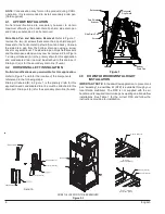
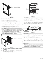
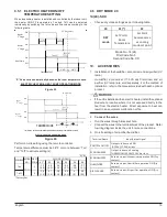
2.
Before removing the coil remove the wire ties holding the
sensor wire harness to the center support. Remove the
insulation covering the wire connectors and disconnect the
wires. Do not cut or damage the insulation covering the
junction connectors since it will be required to secure the
wires once the change is complete. See Figures 2-1 and 2-
2 for wire tie location.
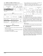
WIRE TIE LOCATION TO BE SECURED
Figure 2-2
*Do not
get the
trap to touch
the coil tubing
(3) Secure the insulated connectors to
the corner using two screws and the
mounting wire ties provide
d .
(2) Connect the
junction connectors
and
slide the insulation
over it.
Secure the insulation on the
junction
using two wire ties.
(1) Insert the junction
connectors into the
insulation
Junction wires
Insulation
Insulation
Sensor wires
Screw
wire tie
Screw
wire tie
(Front view)
(Side view)
Screw
(Front view)
(Side view)
mount
mount
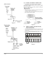
NOTE: DO NOT USE MANIFOLDS OR FLOWRATOR TO PULL
THE COIL ASSEMBLY OUT. FAILURE TO DO SO MAY
RESULT IN BRAZE JOINT DAMAGE AND LEAKS.
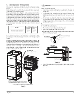
3.
Slide the coil assembly out using the bottom drain pan to
pull the assembly from the cabinet.
4.
For flipping the coil, drain pan extension must be removed
for all models. Center support should not be removed while
removing the drain pan extension. Side drain pan and
horizontal drip shield can be removed for downflow
application. The side drain pan and horizontal drip shield
cannot be removed for horizontal right.
5.
Using the bottom drain pan to hold the coil assembly, slide
the coil assembly back into the cabinet on the downflow
brackets as shown in Figure 9.
6.
Reconnect the sensor wires and replace the insulation
securing it with wire ties on both sides as shown in Figure 2-
2. Then, secure the wire harness to the corner post using
the screw mount wire ties provided.
7.
Re-install the access panels removed in Step 1.
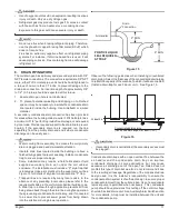
8.
Two drain ports located at the bottom drain pan (horizontally
oriented) are to be used for upflow and downflow applications
and the two on the side drain pan (vertically oriented) are to
be used when the unit is in horizontal right or left
configuration. When the unit is in upflow or downflow
configuration, the drain ports located on bottom drain pan
must be plugged and vice versa. Drain ports located at lower
elevation (closer to the ground) in either configuration must
be connected to the main drain line and the higher is for the
secondary drain line.