


4
English
(d)
Where flammable gas may leak, where there is
carbon fiber, or ignitable dust suspension in the
air, or where volatile flammables such as thinner
or gasoline are handled. Operating the unit in such
conditions can cause a fire.
•
Take adequate measures to prevent the outside unit from
being used as a shelter by small animals. Small animals
making contact with electrical parts can cause
malfunctions, smoke, or fire. Instruct the customer to
keep the area around the unit clean.
•
Install the power supply and control wires for the indoor
and outdoor units at least 3.5 feet away from televisions
or radios to prevent image interference or noise.
Depending on the radio waves, a distance of 3.5 feet
may not be sufficient to eliminate the noise.
•
Dismantling the unit, treatment of the refrigerant, oil and
additional parts must be done in accordance with the
relevant local, state, and national regulations.
•
Do not use the following tools that are used with
conventional refrigerants: gauge manifold, charge hose,
gas leak detector, reverse flow check valve, refrigerant
charge base, vacuum gauge, or refrigerant recovery
equipment.
•
If the conventional refrigerant and refrigerator oil are
mixed in R-410A, the refrigerant may deteriorate.
•
This air conditioner or heat pump is an appliance that
should not be accessible to the general public.
•
As design pressure is 450 psi, the wall thickness of field-
installed pipes should be selected in accordance with
the relevant local, state, and national regulations.
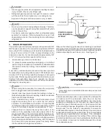
2.
BEFORE INSTALLATION
•
Entrust installation to the place of purchase or a qualified
serviceman. Improper installation could lead to leaks and, in
worse cases, electric shock or fire.
•
Use of unspecified parts could lead to the unit failing, leaks
and, in worse cases, electric shock or fire.
•
Be sure to read this manual before installing the indoor unit.
•
Be sure to mount an air filter (part to be procured in the field)
in the suction air passage in order to prevent water leaking,
etc.
The accessories needed for installation must be retained in
your custody until the installation work is completed. Do
not discard them.
1.
Decide upon a line of transport.
2.
Leave the unit inside its packaging while moving, until
reaching the installation site. Where unpacking is
unavoidable, use a sling of soft material or protective plates
together with a rope when lifting, to avoid damage or
scratches to the unit.
Be sure to check the type of R-410A refrigerant to be used
before installing the unit.
(Using an incorrect refrigerant will prevent normal operation
of the unit.)
For the installation of an outdoor unit, refer to the installation
manual attached to the outdoor unit.
2.1
PRECAUTIONS
•
Be sure to instruct customers how to properly operate the
unit (operating different functions, and adjusting the
temperature) by having them carry out operations themselves
while looking at the operation manual.
•
Do not install in locations where the air contains high levels
of salt such as that near the ocean and where voltage
fluctuates greatly such as that in factories, or in vehicles or
vessels.
2.2
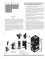
OPTIONAL ACCESSORIES
This indoor unit requires one of the operation remote controls
listed below.
Wired type
BRC1E73, BRC2A71
Remote Controller
FOR THE FOLLOWING ITEMS, TAKE SPECIAL CARE
DURING CONSTRUCTION AND CHECK AFTER
INSTALLATION IS FINISHED.
ITEMS TO BE CHECKED AFTER COMPLETION OF WORK


