


18
English
For installations not indicated above the following formula
is to be used:
TR = (kW x 3412) x (Voltage Correction) / (1.08 x CFM)
Where:
TR
= Temperature Rise
kW
= Heater Kit Actual kW
3412
= Btu per kW
VC*
= .96 (230 Supply Volts)
= .92 (220 Supply Volts)
= .87 (208 Supply Volts)
1.08
= Constant
CFM
= Measured Airflow
*VC (Voltage Correction)
NOTE:
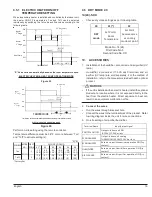
The Temperature Rise Calculations can also be used
to estimate the air handler airflow delivery. When using these
tables for this purpose set the room thermostat to maximum
heat and allow the system to reach steady state conditions.
Insert two thermometers, one in the return air and one in the
supply air. The temperature rise is the supply air temperature
minus the return air temperature. Using the temperature rise
calculated, CFM can be estimated from the TR formula above.
See Specification Sheet and/or Service Manual for more
information.
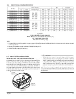
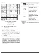
11(21)-3-XX
XX
01 (*)
02
07
08
Heater Operation
Electric
Heater
with Heat
Pump not
allowed
Electric
Heater
with Heat
Pump
allowed
Electric
Heater
with Heat
Pump not
allowed
Electric
Heater
with Heat
Pump
allowed
Electric Heater run
for Defrost/oil
return operation
Not
Allowed
Not
allowed
Allowed
Allowed
*Factory Set
Electric Heater Setting
Mode No. 11(21)
First Code No. 3
Second Code No. XX
No Heat Kit
3
5
6
8
10
15
19
01*
02
03
04
05
06
07
08
FTQ18TAVJUA
X
X
X
X
X
X
FTQ18TAVJUD
X
X
X
X
X
X
FTQ24TAVJUA
X
X
X
X
X
X
FTQ24TAVJUD
X
X
X
X
X
X
FTQ30TAVJUA
X
X
X
X
X
X
FTQ30TAVJUD
X
X
X
X
X
X
FTQ36TAVJUA
X
X
X
X
X
X
FTQ36TAVJUD
X
X
X
X
X
X
FTQ42TAVJUA
X
X
X
X
X
X
X
FTQ42TAVJUD
X
X
X
X
X
X
X
FTQ48TAVJUA
X
X
X
X
X
X
X
FTQ48TAVJUD
X
X
X
X
X
X
X
*
Factory Set
X
Available
Not Available
HEATER (kW)
Second Code No.
Model
Mode No.
First Code No.
11(21)
5


