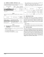


19
English
9.5.1
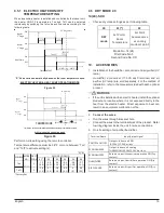
ELECTRIC HEATER ON/OFF
TEMPERATURE SETTING
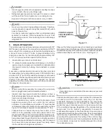
When an auxiliary heater is installed and controlled by the indoor unit,
the heater ON/OFF temperatures, Ton and Toff, can be selected
individually by switching the 1st code and 2nd code according
to
the
following table.
Heater
2 Stage
nd
Heater
1 Stage
st
Heat Pump
ON
ON
ON
OFF
OFF
OFF
TEMPERATURE
1.8°F
1.8°F
Toff + S*
Ton + S*
SP (Set Point)
*“
S” Value varies automatically based on the room temperature trend
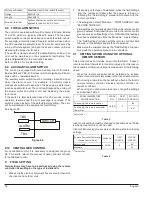
ELECTRIC HEATER & HEAT PUMP OPERATION MODE
Figure 25
ON
OFF
SP (Set Point)
Heater
2
nd
Stage
ON
OFF
1.8
F
1.8
F
Ton + S*
Heater
1
st
Stage
TEMPERATURE
*‘‘S” Value varies automatically based on the room temperature trend
ELECTRIC HEATER OPERATION MODE
Figure 26
Perform on-site setting using the remote controller.
Temperature difference must be 3.6ºF or more between “Ton”
and “Toff” to activate setting(s).
°F (°C)
01*
02
03
04
05
06
Ton
1
-7.2
(-4.0)
-6.3
(-3.5)
-5.4
(-3.0)
-4.5
(-2.5)
-3.6
(-2.0)
-2.7
(-1.5)
Toff
2
-3.6
(-2.0)
-2.7
(-1.5)
-1.8
(-1.0)
-0.9
(-0.5)
0
(0)
0.9
(0.5)
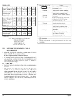
SYMBOL
MODE
NO.
FIRST
CODE
SECONE CODE NO.
11(21)
*Factory Set
9.6
DRY MODE 2.0
14(24)-5-XX
•
Choose dry mode settings as per following table:
XX
01 (*)
02
DRY
mode
Set Point =
Room
Temperature
Set Point
became same
as cooling
mode set point
Mode No. 14(24)
First Code No. 5
Second Code No. XX
10.
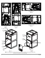
ACCESSORIES
1.
Installation of the humidifier, economizer and air purifier (UV
lamp)
Humidifier, economizer (11.5VA each terminal) and air
purifier (UV lamp) are sold separately. For the method of
installation, refer to the manual provided with each optional
product.
•
If the unit is installed with an electric heater, install the optional
product at a location where it is not exposed directly to the
heat from the electric heater. Direct exposure to heat can
result in an equipment malfunction or fire.
2.
Connect the wires.
•
Run the wires through knockout hole.
•
Connect the wires to the terminal block of the product. Refer
to wiring diagram inside the unit for wire connections.
3.
On-site setting of air purifier/humidifier.
Terminal Name
Input/output signal
CONTROL ON/OFF
Outputs: indoor unit ON
(AC 24V) 11.5VA or less
ECONOMIZER 2
Output: indoor unit cooling
THERMO ON (AC 24V) 11.5VA or less
ECONOMIZER 1
Receives input: Economizer operation ON (Dry
contact)
HUMIDIFIER
Receives input: Humidifier operation ON (Dry
contact)
AIR CLEANER
Receives input: Air purifier operation ON (Dry
contact)


