


21
HIGH VOLTAGE!
DISCONNECT ALL POWER BEFORE SERVICING.
MULTIPLE POWER SOURCES MAY BE PRESENT. FAILURE TO DO SO
MAY CAUSE PROPERTY DAMAGE, PERSONAL INJURY OR DEATH.
WARNING
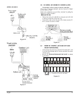
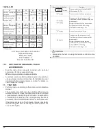
Wiring is subject to change. Always refer to the wiring diagram on the unit for the most up-to-date wiring.
NOTES:
1. PLACE RED WIRES ON 208 V TERMINAL OF 2-TRANSFORMER
(TR1/TR2) FOR 208 VAC OPERATION.
2. MANUFACTURER'S SPECIFIED REPLACEMENT PARTS MUST BE
USED WHEN SERVICING.
3. IF ANY OF THE ORIGINAL WIRES AS SUPPLIED WITH THIS UNIT
MUST BE REPLACED, IT MUST BE REPLACED WITH WIRING
MATERIAL HAVING A TEMPERATURE RATING OF AT LEAST 105°C.
USE COPPER CONDUCTORS ONLY.
4. UNIT MUST BE PERMANENTLY GROUNDED AND CONFIRM TO
N.E.C AND LOCAL CODES.
5. DISCARD CONNECTOR PL1 WHEN INSTALLING OPTIONAL HEAT
KIT.
6. REMOVE SHORT RED CIRCUITING WIRE AND PUT AUX ALARM
SWITCH WHEN INSTALLING AUX ALARM SWITCH.
7. USE N.E.C CLASS 2 WIRE.
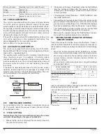
INTEGRATED CONTROL:
POWER/HEATER KIT/
DISCONNECT SWITCH
CONNECTOR
PL1, PL2
COMPONENT CODES:
F1U, F2U
TR1, TR2
TRANSFORMER
FUSE LINK
COLOR CODES:
BL - BLUE
RD - RED
YL - YELLOW
OR - ORANGE
BL - BLACK
GY - GREY
BR - BROWN
GR - GREEN
WH - WHITE
PU - PURPLE
LOW VOLTAGE
LOW VOLTAGE FIELD
HIGH VOLTAGE
HIGH VOLTAGE FIELD
JUNCTION
TERMINAL
PLUG CONNECTION
EQUIPMENT GND
FIELD GROUND
0140A00500-A
X1A
X3A
X38A
BS1
X12A
X13A
HAP
X8A
THERMISTOR
(HEAT EXCHANGER 1, 2)
MPU
MULTI
TENANT
(OPTION)
EEV COIL
M
K1R
K3R
TB6
TB8
K2R
HEATER KIT
OUTPUT
LEARN
PS
TB5
TB4
(ACC-OUT)
3
6
5
9
8
7
10
11
12
RD
BK
RD
BR
BL
BL
RD
FLASH
WRITER
OR
GY
RD
YL
BK
PU
YL
HEATER KIT
BK
GR
GROUND LUG
CONNECTION DISABLED
INSTALLING AUX ALARM (ALARM)
24VAC
COM
COM
208
VAC
230
VAC
208
VAC
230
VAC
TR1
(SEE NOTE 1)
TR2
(SEE NOTE 1)
H2P
(COM STAT)
H3P (RX DATA)
X33A
PCB
(OPTION)
REMOTE SENSOR
(OPTION)
X4A
X35A
X23A
CAPACITY SETTING
X1M
T1
P2
P1
T2
F2
1
2
R
C
ECONOMIZER (OPTION)
HUMIDIFIER (OPTION)
AIR CLEANER (OPTION)
EXTERNAL CONTACT (OPTION)
OUTPUT FOR
CONTROL ON/OFF
(OPTION)
OUTPUT FOR
ECONOMIZER 2
(OPTION)
X7A
FAN
1
ECM MOTOR
BK
RD
PL1
PL2
9
3
2
6
5
4
7
8
1
BK
RD
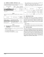
DISCONNECT SWITCH WIRING
PL1
PL2
9
7
8
4
5
6
3
2
1
PL3
PL4
TRANSFORMER
CONNECTOR
PL3, PL4
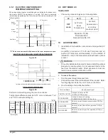
RELAY IN
(ACC-IN)
BK
RD
GY BL
X5A
TB1
TH1
TB2
TR1
TB10
TB3
TH2
TR2
TB7
COM
F1U
F2U
SEE NOTE 7
TB5
TB4
~ ~
WH
BR
BL
GR
RD
BK
BK
RD
RD
208/230
VAC
~ ~
TRANSMISSION WIRING
REMOTE CONTROLLER WIRING
(SEE NOTE 4)
(SEE NOTE 5)
TO
24VAC
BK
2
4
WH
(SEE NOTE 6)
WIRING ADAPTER
INDOOR UNIT PCB
RD
F1
MOTOR
X2M
RELAY OUT
12. Wiring Diagram


