


13
English
8.5
ELECTRICAL CONNECTIONS
IMPORTANT NOTE: USE COPPER CONDUCTORS ONLY.
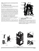
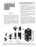
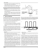
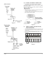
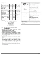
Knockouts are provided on the air handler top panel and sides
of the cabinet to allow for the entry of the supply voltage
conductors, as shown in Figure 17. If the knockouts on the cabinet
sides are used for electrical conduit, an adapter ring must be
used in order to meet UL1995 safety requirements. An NEC or
CEC approved strain relief is to be used at this entry point. Some
codes/municipalities require the supply wire to be enclosed in
conduit. Consult your local codes.
Side of
Cabinet
Top of
Cabinet
Figure 17
•
Outside the air conditioner, do not route the remote controller
wiring and transmission wiring together with other electrical
wiring. Keep the remote controller wiring and transmission
wiring at least 2 in. (50mm) away from the power wiring and
other electrical wiring. Effects of electrical interference
(external noise) may result in malfunction and breakdown.
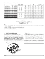
If the power supply voltage is 208V, change the transformer wire
connection from the 240V terminal to the 208V terminal on both
transformers.
8.4
ELECTRICAL CHARACTERISTICS
Hz
Volts
MCA
MOP
HP
FLA
Cooling
Heating
60
208/230V
4.9
15
1/2
3.9
215
215
60
208/230V
4.9
15
1/2
3.9
273
273
60
208/230V
4.9
15
1/2
3.9
407
407
60
208/230V
4.9
15
1/2
3.9
436
436
60
208/230V
6.5
15
3/4
5.2
473
473
60
208/230V
6.5
15
3/4
5.2
518
518
60
208/230V
4.9
15
1/2
3.9
215
215
60
208/230V
4.9
15
1/2
3.9
273
273
60
208/230V
4.9
15
1/2
3.9
407
407
60
208/230V
4.9
15
1/2
3.9
436
436
60
208/230V
6.5
15
3/4
5.2
473
473
60
208/230V
6.5
15
3/4
5.2
518
518
FTQ24TAVJUD
FTQ30TAVJUD
FTQ36TAVJUD
FTQ42TAVJUD
FTQ48TAVJUD
Max. 229V
Min. 187V
Max. 253V
Min. 209V
Max. 229V
Min. 187V
Max. 253V
Min. 209V
FTQ24TAVJUA
FTQ30TAVJUA
FTQ36TAVJUA
FTQ42TAVJUA
FTQ48TAV JUA
FTQ18TAVJUD
Model
Power Supply
IFM
Input (W)
Voltage Range
FTQ18TAVJUA
Symbols:
MCA: Minimum Circuit Amps (A)
MOP: Max Overcurrent Protective Device (A)
HP: Fan Motor Output (W)
FLA: Full Load Amps (A)
Notes:
1. Voltage Range: Units are suitable for use on electrical Systems where voltage supplied to unit terminals is not below or above
listed range limits.
2. Maximum allowable voltage imbalance between phases is 2%.
3. Select wire size based on the MCA.


