background image

Installation manual

8

Be sure to insulate the liquid and gas-side field piping and the
refrigerant branch kit.

(The highest temperature that the gas-side piping can reach is
around 120°C, so be sure to use insulating material which is
very resistant.)

Cautions for flare connection

Please refer to the table for the dimensions for processing flares
and for the tightening torques. (Too much tightening will end up
in splitting of the flare.)

If a torque wrench is not available, be aware that the tightening
torque may increase suddenly. Do not tighten nuts any further
than to the angle as listed.

When connecting the flare nut, coat the flare inner surface with
ether oil or ester oil and initially tighten 3 or 4 turns by hand
before tightening firmly.

After completing the installation, carry out a gas leak inspection
of the piping connections with nitrogen and such.

Cautions for necessity of a trap

Since there is fear of the oil held inside the riser piping flowing back into
the compressor when stopped and causing liquid compression
phenomenon, or cases of deterioration of oil return, it will be necessary
to provide a trap at an appropriate place in the riser gas piping.

Trap installation spacing. 

(See figure 6)

A

Outdoor unit

B

Indoor unit

C

Gas piping

D

Liquid piping

E

Oiltrap

H

Install trap at each difference in height of 10 m.

A trap is not necessary when the outdoor unit is installed in a
higher position than the indoor unit.

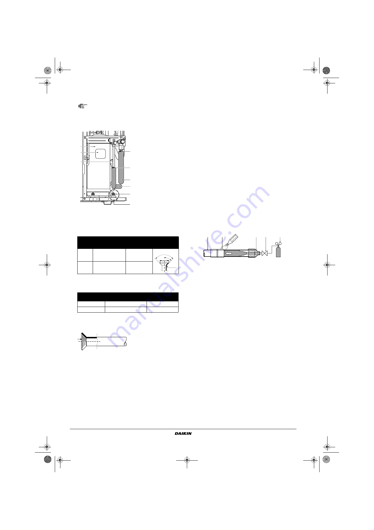
Cautions for brazing

Be sure to carry out a nitrogen blow when brazing.
Brazing without carrying out nitrogen replacement or releasing
nitrogen into the piping will create large quantities of oxidised
film on the inside of the pipes, adversely affecting valves and
compressors in the refrigerating system and preventing normal
operation. When brazing pipes however, do not use oxidation
preventers. Residue of such preventers may result in choking of
pipes or malfunction of components.

When brazing while inserting nitrogen into the piping, nitrogen
must be set to 0.02 MPa with a pressure-reducing valve (=just
enough so that it can be felt on the skin).

Evacuating

Do not purge the air with refrigerants. Use a vacuum pump to
vacuum the installation. No additional refrigerant is provided for
air purging.

Pipes inside the units were checked for leaks by the
manufacturer. The refrigerant pipes fit on site are to be checked
for leaks by the installer.

Confirm that the valves are firmly closed before leak test or
vacuuming.

Set up for vacuuming and leak test: 

see 

figure 8

Any exposed piping may cause condensation or burns
if touched.

Piping 

size

Flare nut 

tightening torque

A - dimensions for 

processing flares 

(mm)

Flare shape

Ø9.5

33~39 N•m

12.8~13.2

Ø15.9

63~75 N•m

19.3~19.7

Piping size

Further tightening angle

Recommended arm 

length of tool

Ø9.5

60°~90°

200 mm

Ø15.9

30°~60°

300 mm

2

1

3

5

5

A

4

4

6

1

Compressor

2

Terminal cover

3

Indoor and outdoor 
field piping

4

Corking, etc.

5

Insulation material

6

Bolts

A

Be careful with pipe, 
bolt and outer panel 
connections

R=0.4~0.8

45

° ±

2

90

°±

2

A

1

Refrigerant piping

2

Part to be brazed

3

Taping

4

Hands valve

5

Pressure-reducing valve

6

Nitrogen

A

Pair system

B

Simultaneous operation system

1

Pressure gauge

2

Nitrogen

3

Refrigerant

4

Weighing machine

5

Vacuum pump

6

Stop valve

7

Main pipe

8

Branched pipes

9

Pipe branching kit (optional)

1

2

3

4

5

6

6

4PEN342104-1B.book  Page 8  Tuesday, May 26, 2015  9:07 AM

Summary of Contents for RZQS71D2V1B

Page 1: ...INSTALLATION MANUAL RZQSG71L3V1B RZQS71D7V1B RZQS71D2V1B RZQS100D7V1B RZQS125D7V1B RZQS140D7V1B Split System air conditioners 4PEN342104 1B book Page 1 Tuesday May 26 2015 9 07 AM ...

Page 2: ...E B C D H H1 L1 H1 H2 L3 L1 L2 H1 H2 L4 L1 L3 L2 H1 H2 L7 L1 L6 L5 L4 L3 L2 A A B2 B2 B2 C C D1 D1 D1 D2 D2 D2 D2 D2 E E H H L1 L1 L1 L2 L2 L2 A A B1 B1 B1 B1 B1 B1 B2 B2 B2 C C D1 D1 D1 D2 D2 D2 D2 D2 E E H H L1 L1 L1 L2 L2 L2 1 1 2 1 2 3 4 5 7 8 9 6 4PEN342104 1B book Page 1 Tuesday May 26 2015 9 07 AM ...

Page 3: ...giudicato positivamente da B secondo il Certificato C 07 Σημείωση όπως καθορίζεται στο A και κρίνεται θετικά από το B σύμφωνα με το Πιστοποιητικό C 08 Nota tal como estabelecido em A e com o parecer positivo de B de acordo com o Certificado C 09 Примечание как указано в A и в соответствии с положительным решением B согласно Свидетельству C 10 Bemærk som anført i A og positivt vurderet af B i henho...

Page 4: ...e com o parecer positivo de B de acordo com o Certificado C 09 Примечание как указано в A и в соответствии с положительным решением B согласно Свидетельству C 10 Bemærk som anført i A og positivt vurderet af B i henhold til Certifikat C 11 Information enligt A och godkänts av B enligt Certifikatet C 12 Merk som det fremkommer i A og gjennom positiv bedømmelse av B ifølge Sertifikat C 13 Huom jotka...

Page 5: ...lectrical work is carried out by qualified personnel according to the local laws and regulations and this installation manual using a separate circuit Insufficient capacity of the power supply circuit or improper electrical construction may lead to electric shocks or fire Make sure that all wiring is secure using the specified wires and ensuring that external forces do not act on the terminal conn...

Page 6: ...is appliance is intended to be used by expert or trained users in shops in light industry and on farms or for commercial use by lay persons Sound level is less than 70 dB A Provide a logbook In accordance with the relevant national and international codes it may be necessary to provide a logbook with the equipment containing at least info on maintenance repair work results of tests stand by period...

Page 7: ...en a strong wind blows continuously on the face of the unit the fan can start rotating very fast until it breaks Refer to the figures for installation of this unit in a place where the wind direction can be foreseen Turn the air outlet side toward the building s wall fence or screen Set the outlet side at a right angle to the direction of the wind 3 Prepare a water drainage channel around the foun...

Page 8: ...ocket optional Make sure the drain works properly Installation servicing space The numerical figures used in here represent the dimensions for the 71 100 125 140 class models Figures between indicate the dimensions for the 100 125 140 class models Unit mm Refer to Precautions on installation on page 4 Precaution A In case of non stacked installation See figure 1 B In case of stacked installation 1...

Page 9: ...ipe sizes must have the same size as the connected indoor units pipe sizes Branch see marking on figures 3 4 and 5 Selection of branch pipe L A L H 0 L 1 2H 150 250 1 2H L 200 300 H L Installation impossible Installation shall be done by a licensed refrigeration technician the choice of materials and installation shall comply with the applicable national and international codes In Europe EN378 is ...

Page 10: ...Length of branch pipe to the indoor unit should be as short as possible Try to keep lengths of both branch pipes to the indoor unit equal Refrigerant piping Field pipes can be installed in four directions Figure Field pipes in four directions Cutting out the two slits makes it possible to install as shown in the figure Field pipes in four directions Use a metal saw to cut out the slits To install ...

Page 11: ...r handling the valve cover The valve cover is sealed where indicated by the arrow Refer to the figure Take care not to damage it After operating the valve be sure to tighten the valve cover properly Check for refrigerant leakage after tightening the cap Cautions for handling service port Always use a flexible charge hose with a push rod and valve to enable recovery of remaining refrigerant in the ...

Page 12: ...iping will create large quantities of oxidised film on the inside of the pipes adversely affecting valves and compressors in the refrigerating system and preventing normal operation When brazing pipes however do not use oxidation preventers Residue of such preventers may result in choking of pipes or malfunction of components When brazing while inserting nitrogen into the piping nitrogen must be s...

Page 13: ...e vacuum pump with a non return valve which can evacuate to 100 7 kPa 5 Torr 755 mm Hg Evacuate the system from the liquid and gas pipes by using a vacuum pump for more than 2 hours and bring the system to 100 7 kPa After keeping the system under that condition for more than one hour check if the vacuum gauge rises or not If it rises the system may either contain moisture inside or have leaks The ...

Page 14: ...e pumping down operation make sure to have removed the insulation sheet that was placed in the switch box as a protective measure as in chapter Preliminary measures on page 10 When in need of operation turn off the main power supply and turn it on again Make sure that stop valves both on liquid and gas side are open and be sure to operate the unit in cooling operation during test run Liquid piping...

Page 15: ... stop valve attachment plate one more time along with the electric wiring and the inter unit wiring Lay the electrical wiring so that the front cover does not rise up when doing wiring work and attach the front cover securely When cables are routed from the unit a protection sleeve for the conduits PG insertions can be inserted at the knock out hole See figure 7 When you do not use a wire conduit ...

Page 16: ...washer RZQSG71 RZQS71 RZQS100 RZQS125 RZQS140 Minimum circuit amps MCA a a Stated values are maximum values see electrical data of combination with indoor units for exact values 21 2 18 9 27 6 28 8 Recommended field fuse A 25 20 32 Wire type b b Only in protected pipes use H07RN F when protected pipes are not used H05VV U3G Size Wiring size must comply with the applicable local and national code W...

Page 17: ... receiver first 5 In case the panels of indoor units are not yet installed to the indoor units make sure to shut off the power supply after finishing the complete test run 6 A complete test run surely includes shutting off power after having performed a normal operation stop on the remote controller Do not stop operation by turning circuit breakers off Failure diagnosis at the moment of first inst...

Page 18: ...stor coil middle R6T Thermistor liquid R10T Thermistor fin RC Signal receiver circuit S1NPH Pressure sensor high S1PH Pressure switch high TC Signal transmission circuit V1R Power module V2R V3R Diode module V1T Insulated gate bipolar transistor X1M Terminal strip X6A Connector option Y1E Expansion valve Y1S 4 way valve Z1C Z3C Noise filter Z1F Z4F Noise filter Wire clamp BLK Black Terminal GRN Gr...

Page 19: ...4PEN342104 1B book Page 1 Tuesday May 26 2015 9 07 AM ...

Page 20: ...4P342104 1B 2015 05 Copyright 2013 Daikin 4PEN342104 1B book Page 1 Tuesday May 26 2015 9 07 AM ...

Reviews: